Parameters 'r' of Transistors in Low Frequencies :
7. - PARAMETERS 'r'
Other parameters, most often used for transistors at low frequencies and low power, are designated by the symbol r because they are all homogeneous resistors and their values are expressed in Ω or kΩ.
This system consists of three parameters expressed in Ω and the pure number or coefficient or called hfb. They are designated by the symbols re, rb and rc because they respectively represent the values of the internal resistances of the transistor for the emitter, the base and the collector. Since a separation of the three internal resistances is not physically possible, but only theoretically, it is understood that these parameters can not be measured in practice as was done for the parameters h ; we can only calculate their value starting, for example, from the parameters h.
One of the advantages of the r parameters is to allow simpler formulas to be obtained when designing amplifiers and circuits in general.
Another advantage is due to the fact that these parameters keep the same value in common base assembly and therefore that unlike the parameters h, there is no need to differentiate the common base parameters of the common transmitter parameters.
Sometimes, in the manufacturer's manuals, only the values of the parameters r and the coefficient hfb or ,
are indicated, while it may be interesting to know the values of the parameters h relating to the common base and common transmitter assembly.
These can be easily deduced from the first ones by using the following formulas in which the values of rb and re must be expressed in Ω and the value rc in kΩ ; in this way, the parameters hib and hie are expressed in Ω and the parameters hob and hoe in µA / V, that is to say in µS (microsiemens).
For the common base assembly, we have :
hib = re + rb x (1 - )
hfb =
hrb = rb / (1 000 x rc)
hob = 1 000 / rc
For the common transmitter assembly, we have :
hie = rb + re x (1 - )
hfe =
/ (1 -
)
hre = re / (1 000 x rc) x (1 - )
hoe = 1 000 /
rc x (1 - )
The parameters r are obtained from the parameters h relating to the common transmitter assembly by the following relations :
rb = hie - (hre / hoe) x (1 + hfe)
rc = (1 + hfe) / hoe
re = hre / hoe
= hfe / (1 + hfe)
Having obtained the parameters r, we can calculate the parameters hb with the formulas seen previously ; thus, in two calculation steps it is possible to obtain the parameters hb relating to the common base assembly which are not always available, starting from those of the common transmitter assembly he.
for example:
For hie = 1,1 kW
; hfe = 50 ; hre = 0,00025 ; hoe = 25 µS.
We obtain the following parameters r
suivants :rb = 590 W
; rc = 2,04 MW ; re = 10 W
; = 0,98 and the parameters
hb
are so :hib = 21,6 W ;
hfb = 0,98 ; hrb = 0,00029 ; hob = 0,49 µS.
Finally, one can search the hc parameters relative to the common collector assembly. They are easily calculated from the parameters he using the following formulas :
hic = hie
hrc = 1 - hre
hfc = 1 + hfe
hoc = hoe
In the previous case, we get :
hic = 1,1 kW ; hfc = 51 ; hrc = 0,99975 ; hoc = 25 µS.
It should be noted that in this arrangement where the voltage gain is substantially equal to 1, the reaction coefficient hrc is also almost equal to 1 and this independently of the other parameters.
To conclude, Figure 9 shows the curves that give the parameters of the transistor at low frequencies and low signals (low power) type BC 108, depending on the collector current and for two values of the collector voltage (VCE = 5 V and VCE = 10 V).
8. - PARAMETERS OF TRANSISTORS USED IN HIGH FREQUENCY
The four parameters seen above are not sufficient to precisely determine the characteristics of a transistor intended to operate at high frequencies. Indeed, for such types of transistors, it is no longer possible to neglect the capacity of the junctions which, although relatively low values, have at low frequencies quite low impedances. This impedance can have a significant influence on the input and output resistors of the transistor.
In addition to the parameters that are valid at low frequencies, it is necessary to take into account the junction capacities, that is, the input and output capacities, which brings to six the total number of parameters.
As can be seen in Figure 10-a, in the case of the common base circuit, the input capacitance coincides with the capacity of the emitter-base junction and that of the output with the capacity of the collector-base junction.
In the case of the common transmitter arrangement, the input capacitance also coincides with the capacity of the transmitter-base junction while the output capacity, which is more complex, is due to the other two junctions.
The input and output impedances of the transistor are therefore given by the paralleling of a resistor r and the reactance presented by the capacitor C at the operating frequency considered.
Since these two elements are in parallel, it is necessary to consider the admittances rather than the impedances so as to simply perform the sum of the conductance g = 1 / r, due to the resistive component and the susceptance b = 2 x n x f x C of the capacitive component.
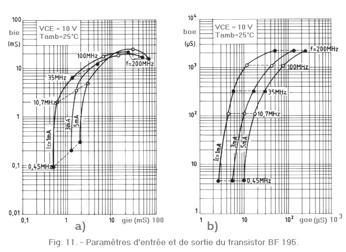
Generally therefore, instead of giving the admittance Y, the constructor indicates the values of the components g and b for different frequencies. We report b on the vertical axis and g on the horizontal axis of a diagram in which each point corresponds to a determined value of the frequency. An example of a diagram relating to the transistor BF 195, used in the high frequency and intermediate frequency circuits of the radio receivers, is given in Figure 11.
Some frequency values have been indicated : 0.45 MHz and 10.7 MHz represent the intermediate frequencies used in radio receivers respectively for amplitude modulation and frequency modulation; 100 MHz represents one of the possible transmission frequencies in frequency modulation (frequency band between 87 and 108 MHz).
With regard to the amplification and reaction coefficients, they are here defined as the ratio between the variations of the collector (or base) current and those of the base (or collector) voltage ; they are also admittances.
The amplification coefficient Yfe is given by the ratio between the IC
variation of the collector current and the variation VBE
of the corresponding basic voltage, namely :
Yfe =
IC / VBE
This parameter is generally expressed in mS (millisiemens), IC being expressed in mA and VBE in V (or IC in µA and VBE in mV).
On the other hand, the reaction coefficient Yre is defined as the ratio of the variation of the basic current IB
and the variation of the collector voltage which causes it, namely :
Yre =
IB/ VCE
This coefficient is generally expressed in µS (microsiemens), that is to say the ratio between µA and V.
Since the variations of the current and the voltage are not in phase (because of the internal capacitances of the transistor), it is necessary to specify this phase shift which we call ; thus, an angle fe will correspond to the parameter Yfe and an angle re will correspond to the parameter Yre.
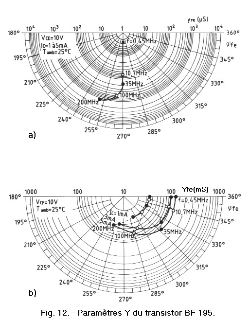
The values of Yfe, fe, Yreand re
vary with the frequency ; they are therefore obtained from graphs such as those of Figure 12-b and Figure 12-a.
In these polar coordinates, the values of fe
are read from the angular value indicated on the circumference and the modulus of Y on one of the radii.
Finally, it should be noted that these parameters called parameters Y (since Y is the symbol of the admittance) also depend on the collector current of the transistor ; it is therefore necessary to have different curves, each of them corresponding to a given value of IC.
By way of example, if it is desired to know the parameters Y of the transistor BF 195 when it operates with a collector current of 1 mA at the frequency of 10.7 MHz, it suffices to consider on the various graphs the Figure 11 and Figure 12 the points indicated by 10.7 MHz on the curves marked by 1 mA.
The following values are thus obtained :
gie = 0,6 mS (figure 11-a),
bie = 2 mS (figure 11-a),
goe = 110 µS (figure 11-b),
boe = 110 µS
(figure 11-b),
Yre = 65 µS (figure 12-a),
re = 270°
(figure 12-b),
Yfe= 35 mS (figure 12-b),
fe
= 352° (figure 12-b).
These parameters are used for the calculation of the gain and the impedances of input and output of the amplifiers HF as well as for the verification of their stability.
The next lesson of Semiconductors N° 7 will deal with various semiconductors such as uni-junction transistors, thyristors, diac and triac. Then we will begin the new digital electronics lessons without forgetting PRACTICE.


 Parameters of transistors used in high frequency
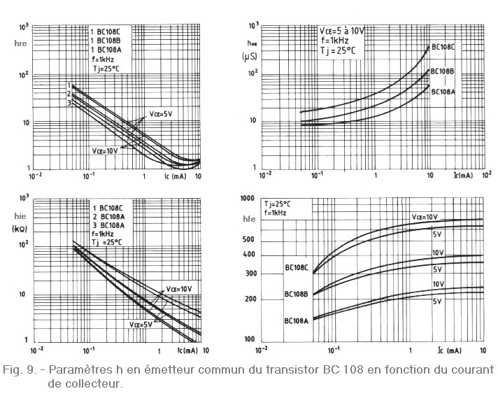
 Click here for the next lesson or in the summary provided for this purpose.
 Top of page
 Next Page