In a previous lesson, we looked at the simplest component that exists : The resistance. We will now see another component as essential as resistance in electronic circuits : the capacitor.
1. - THE CAPACITORS
They are formed by two opposite conductive plates, called armatures and separated by an insulator which is called dielectric. For a given type of dielectric, the larger the area of the armatures or the distance between them, the greater the capacity of the capacitor.
The capacitors can be fixed or variable and listed according to the dielectric as shown in the table in Figure 1. Depending on the type of dielectric, we define the electrical and mechanical characteristics (dimensions and arrangement of the terminals) according to which we will make correct use of the capacitor.
1. 1. -ELECTRICAL CHARACTERISTICS OF THE CAPACITORS
The most important electrical characteristics to know in order to make the best use of the capacitors are given below :
Capacity ;
Tolerance ;
Operating voltage
in direct current ;
in alternating current ;
Test voltage ;
Temperature coefficient ;
Insulation resistance ;
Leakage current ;
Loss angle.
Now let's look at each of the features listed. The capacity is the nominal value that a capacitor presents between its two armatures ; it is measured in farads (symbol F), but this unit corresponds to a too large capacity which one hardly meets in practice ; this is why we frequently use the sub-multiples of farad : millifarad (mF), microfarad (µF), nanofarad (nF) and picofarad (pF).
The relationships between these submultiples are shown in the table in Figure 2.
Looking at this table, it seems obvious first of all that nanofarad (nF) is equivalent to kilopicofarad (kpF) ; indeed for these two units, the same multipliers are used.
The first column indicates the units of measurement of the capacitors which one wants to convert into another unit by referring to the corresponding column and by multiplying by the coefficient of the same line.
Let's see some examples to better interpret the table in Figure 2 and clarify above :
0,47 µF x 1 000 = 470 nF = 470 kpF ;
0,47 µF x 1 000 000 = 470 000 pF ;
22 nF x 0,001 = 0,022 µF ;
33 nF x 1 000 = 33 000 pF ;
8 200 pF x 0,001 = 8,2 nF ;
0,0027 µF x 1 000 000 = 2 700 pF ;
0,0027 µF x 1 000 = 2,7 nF = 2,7 kpF ;
1 500 pF x 0,000 001 = 0,0015 µF.
The tolerance is a percentage more or less around the nominal value, which the manufacturer undertakes to respect for all the parts delivered. These are new parts before use, because thereafter variations may be greater after prolonged operation.
The operating voltage in continuous current (symbol VNCC, abbreviation of nominal voltage in direct current) indicates the value of the direct voltage (in volts) which can be applied to the capacitor in steady state.
The operating voltage in alternating current (symbol VNCA, abbreviation of nominal voltage in alternating current) indicates the peak value of the alternating frequency voltage between 50 and 60 Hz which can be applied to the capacitor in steady state.
The test voltage expresses the maximum voltage in volts applicable to the capacitor exclusively for a test to be carried out according to specific procedures established by the manufacturer.
The test voltage indicated by VP is generally 2.5 times greater than the operating voltage VN. Therefore, for a capacitor with VP of 1 500 V, it is possible to apply a maximum operating voltage VN of 1 500 / 2.5 = 600 Volts.
The temperature coefficient indicates the relative change in capacity compared to the change in temperature. It is expressed in parts per million per centigrade degree (ppm / °C) or in millionths per degree Celsius.
When the coefficient is negative, the number expressed is preceded by the sign "-" or the letter N (negative) ; when it is positive, this number is preceded by the sign "+" or the letter P (positive). The acronym NPO indicates that the temperature coefficient is zero.
For example, for a capacitor with a value of 500 nF at 25 °C having a temperature coefficient of - 75 ppm / °C, the capacity decreases by 37.5 pF with each degree of increase in temperature :
This coefficient must be as small as possible in order to minimize variations in capacity as a function of temperature.
Let us remember on this subject that the temperature inside a device can be much higher than the ambient one because of the calorific energy dissipated by other components belonging to the same circuit as the condenser.
On the other hand, in certain cases, the temperature coefficient must have a well-defined value to compensate for the effect of variations in other components of the same circuit.
The insulation resistance is measured by applying a DC voltage across the capacitor, the value of which is specified by the manufacturer ; this data, expressed in megohms as a function of the value of the capacitance, defines in practice the quality of the dielectric : the higher its value, the better the insulation.
Leakage current is a typical datum for electrolytic capacitors; it indicates the value of the current expressed in microamperes (µA), which circulates by the leakage resistance of the dielectric of a charged capacitor. The lower this value, the higher the quality of the capacitor.
The loss angle The
angle is the 90° complement to the phase shift angle between the two alternative quantities V and I.
We therefore see that in a real capacitor, the phase shift angle is less than 90° whereas for an ideal capacitor, the loss angle is zero because the phase shift between V and I is precisely 90°. The loss factor is often used when calculating the tangent. The angle , indicated in %, to express the quality of a capacitor : the lower the percentage, the better the component.
The manufacturing techniques used by capacitor manufacturers to meet the different requirements imposed by their use are very numerous. It can be said that capacitors are the components that are made with the greatest variety of shapes and dimensions. There are capacitors with a cylindrical body, in the form of a disc, a wafer, a drop ... ; for each form, the capacity - volume ratio can be very different according to the manufacturers and no standard governs this.
We will now examine the most common types of capacitor using the dielectric used as a guide.
2. 1. - PAPER AND ALUMINUM CAPACITORS
These capacitors consist of the winding of two very thin sheets of aluminum separated by several sheets of paper impregnated with oil or paraffin. The two sheets in very pure aluminum (99.99%), to avoid oxidation during the manufacture, constitute the reinforcements while the insulation interposed between them forms the dielectric (Figure 3-a, below).
The capacitance of the capacitor is greater the larger the area of the facing plates and the smaller the distance between them. The maximum voltage applicable to the armatures depends on the thickness of the dielectric and its insulating properties.
The winding obtained can be hermetically sealed in an envelope of glass, plastic, tinned brass ... ; two terminals welded to the armatures provide the external connection.
This type of capacitor has a serious drawback because its armatures, being wound on themselves, cause the appearance of an inductor in series with the capacitance of the capacitor for high frequencies.
To remedy this, one generally proceeds by metallizing the edge projecting from each frame, by cathodic evaporation with copper. The output terminals are welded to this metallization. Non inductive capacitors are obtained ; the contact is perfect and the size reduced.
The capacitance values are generally between 500 pF and 0.5 µF with some exceptions for certain specific types. The nominal voltage values range from 125 VN to 1 000 VN.
In current applications, these capacitors have been replaced by plastic film models, of smaller dimensions.
2. 2. - PLASTIC FILM CAPACITORS
These condensers are similar to the preceding ones, but their dielectric is constituted by a very fine plastic film (Figure 3-c). The dielectrics used are polystyrene (styroflex), polyester (mylar) and polycarbonate.
In order to reduce the volume of the capacitors, we also thought of metallizing the plastic film.
A margin is reserved on one side of the two films in order to be able to metallize the wafer and adopt the manufacturing principle adopted for paper and aluminum capacitors. In this way, a compact capacitor, of low inductance, is obtained, similar to that seen previously but with a capacity value two to four times greater, at equal volume.
External protection can be provided depending on the type of capacitor by a coating of die-cast resin or by metal boxes filled with wax or oil.
Sometimes, the body of the component is marked by a ring (Figure 3-b) so that, in the assemblies involving high voltages, the terminal closest to this mark is at a potential playing the role of shielding for the condenser (this is often the lowest potential).
The range of their capacity is between ten picofarads and ten microfarads ; the stability is good even beyond (85° C) and the nominal voltage values range from 25 Volts to more than 2 000 V.
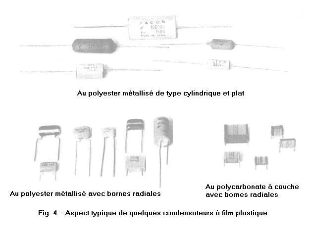
Plastic film capacitors are widely used because they are low cost and have good electrical characteristics ; Figure 4 illustrates the external appearance which they can take to satisfy the numerous manufacturing requirements of electronic devices with printed circuit. The name depends on the manufacturing technique and may vary from one manufacturer to another.
Mica has been used as a dielectric since the early years of manufacturing capacitors ; the first types were made by alternating sheets of mica and very thin sheets of copper or aluminum so as to form a stack which was then compressed and then impregnated with an insulating material. An armature of the capacitor, welded to one of the terminals, is made up of the odd metallic sheets connected together ; the other reinforcement formed of the even sheets is welded to the other terminal (Figure 5-a).
In the new version, the same structure is achieved by depositing a very light layer of silver on the mica sheets. The latter are electrically connected to two metallized faces to which the terminals are welded. The whole is then coated with a molded insulating resin which gives the condenser a rigid structure (Figure 5-b).
These capacitors are characterized by high stability, a very low temperature coefficient and they are particularly suitable for professional use in the HF circuits of measuring instruments. The range of capacities extends from a few picofarads to a few hundred nanofarads for operating voltages from 300 V to more than 2 500 V.
In the consumer sector, mica capacitors have given way to polystyrene capacitors which are not as stable and operate in a more limited temperature range ; in return, they have a smaller footprint and are above all more economical.
Magnesium silicate, alumina and corundum are mixed and finely ground, to which oxides of titanium, barium or strontium are added. The powder obtained is dried, sieved and then molded under pressure with clay or an organic binder and baked at a temperature above 1 000° C.
The parts obtained are enamelled in an electric oven to remove their porosity. The frames are obtained by metallization of silver on both sides.
Protection is normally provided by a layer of lacquered paint baked in the oven. The decoupling capacitors can be vacuum coated with a protective wax to improve their insulation.
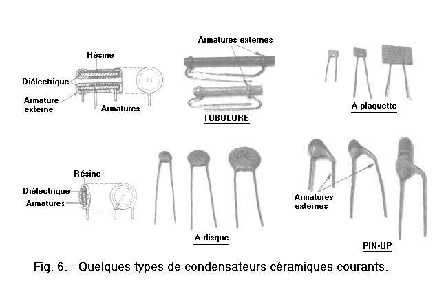
Depending on the appearance of the coating, there are, among others, the tubular, insert, disc, pin-up types (Figure 6).
In tubular ceramic capacitors, the terminal connected to the external reinforcement is sometimes identified by a point or a ring or even set back from the end of the component body.
The variety of external forms and the shape of the terminals (their spacing and their length) are due to the various requirements imposed by the assemblies and the welds which are carried out by automatic operations which one finds on the chains of great series.
The dimensions are related to the capacity and the operating voltage of these capacitors ; however, it happens to have very different capacities (1 pF, 1 nF) for the same dimensions because the dielectric constants are very varied for making ceramics.
To recognize the values, it is therefore necessary to refer to the markings adopted by the manufacturer.
One of the characteristic data of ceramic capacitors is the temperature coefficient which strongly influences the value of the capacity of some of these components, the use of which is prohibited in sharp electronic assemblies. There are still ceramics with very low temperature coefficient, even zero ; very narrow tolerances are also reached and the most common use of these capacitors is decoupling H.F. and U.H.F. due to their low parasitic inductance.
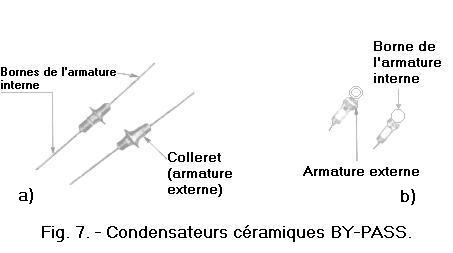
Among the special purpose ceramic capacitors used in H.F. and U.H.F., there are the "BY-PASS" types which are used to decouple wires passing through a chassis or shielding. The collar which represents the external frame is welded to the chassis ; the other armature is connected to two axial terminals which leave at each end of the component (Figure 7-a) or to a terminal in the shape of eyelet (Figure 7-b).
Aluminum electrolytic capacitors belong to the category of fixed wound capacitors.
They differ from other types (paper, plastic film ...) by the fact that a frame (anode) consists of a smooth or engraved aluminum sheet on which a very thin layer of alumina has been deposited. a chemical process. The dielectric is here formed by alumina and the second reinforcement is formed by the electrolyte retained in porous paper sometimes called "blotting paper". The connection with the electrolyte is carried out by means of a second aluminum sheet, called cathode on which is fixed an output terminal. The other armature (anode) also has an output terminal that must be connected to a potential greater than that of the cathode (Figure 8).
Alumina oxide has a high dielectric strength and can be formed in extremely thin layers, so that a high value of capacity per unit volume of the capacitor is obtained. This results in the electrolytic capacitors having a higher capacity than all the other types for equal dimensions and operating voltages.
Electrolytic capacitors are obtained with capacities on the order of 1 µF to more than 10 000 µF with operating voltages ranging from around 3 to 500 V. The tolerance on nominal values is quite wide and can reach up to + 100%.
As we have already specified, these capacitors have the particularity of being polarized and their terminals are identified by the signs (+) and (-). When they are absent, note the terminal which is connected to the aluminum housing (cathode : -) or if it has a throttle to indicate that the nearest terminal is the (anode +).
An electrolytic capacitor is used for filtering or decoupling. A superimposed DC voltage and alternating voltage (50 Hz, 100 Hz or B.F.) are applied to its terminals. The percentage of the AC voltage compared to the DC voltage must not exceed 15% for operating voltages greater than 50 V. In addition, the sum of the DC voltage and the peak AC voltage must not exceed the voltage nominal operating capacitor.
Electrolytic capacitors for alternating current are produced, however, obtained by winding together two formed anodes instead of an anode and a cathode.
The diagram produced is that of two polarized capacitors, opposite and connected in series (Figure 9). The separators are lined (four thicknesses of paper between each electrode). All things being equal, the value of the capacitance obtained is half that of a normal capacitor.
Non-polarized electrolytic capacitors can operate with continuous or alternating quantities.
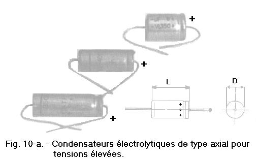
Some electrolytic capacitors of cylindrical shape particularly used for the filtering of rectified electric quantities are illustrated Figure 10-a. The terminals are axial and the aluminum housing can be provided with or without an insulating plastic coating.
The table of the Figure 10-b gives an idea of their dimensions according to their value of capacity and most current operating voltages ; at another manufacturer, these values may change significantly.
Figure 10-b. - Dimensions of overall dimensions of the electrolytic capacitors of the Figure 10-a proportional to the values of most common capacity and operating voltage.
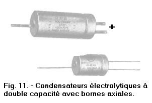
There are also capacitors with two positive and one negative terminals ; they are used in cases where the available space is too small. They are in fact two capacitors enclosed in a cylindrical envelope equipped with three terminals.
The Figure 11 represents this type of double capacitor, one with terminals made of tinned copper wire and the other with terminals made of tabs.
The screw capacitors shown in Figure 12 are used to resist shock and vibration. The plates and the electrolyte are hermetically sealed in a metal case from which the connection terminals come out.
Two electrolytic condensers with screw which differ from each other only by the system of exit of the terminals are illustrated on the Figures 12-a and 12-b ; for the type illustrated on the Figure 12-a, the negative terminal is sometimes absent ; in this case, the electrical connection is obtained by fixing the capacitor by means of a nut on the metal frame of the device which is the earth (0 V) of the electrical circuit.
On the Figure 12-c, one finds a double condenser but which can be screwed. The remark concerning the negative terminal of the Figure 12-a applies to that of the Figure 12-c.
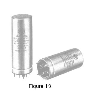
Similar to these, aluminum cylindrical capacitors with pin-shaped mounting lugs for printed circuits, using one as a common negative terminal, for multiple capacitances (Figure 13).
Figure 13. - Multiple capacity electrolytic capacitors with pin mounting lugs for printed circuit.
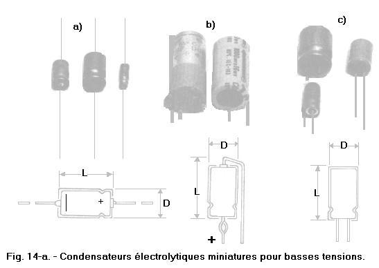
In the apparatuses of reduced dimensions, when particularly compact assemblies are necessary and the voltages in play low, one uses miniature capacitors as on the Figure 14-a.
The external appearance of the most current capacitors of this type with their dimensions according to the capacitive value and the operating voltage is illustrated there in a table Figure 14-b (below).
The terminals can be axial for the horizontal assemblies (see Figure 14-a in top on the left) or vertical (Figure 14-b in top centered) or else axial with exit on the same side for exclusively vertical fixings on printed circuit (Figure 14 -c right).
According to the manufacturer, various reference systems are adopted as can be seen in Figure 15.
More recent in production, tantalum electrolytic capacitors have significantly more advantageous characteristics than those made of aluminum.
First, the dielectric constant of tantalum oxide is about double that of aluminum oxide ; moreover, the film of tantalum oxide is much thinner and has higher stability qualities.
The characteristics show that tantalum capacitors can be used at maximum temperatures of 125° C, while aluminum electrolytic capacitors can only be used up to 85° C.
The dimensions of a tantalum capacitor are significantly smaller than those of its aluminum equivalent for the same capacity and the same operating voltage. Tolerance undergoes the same law and we reach ± 5% with tantalum, a value that cannot be achieved with an aluminum electrolytic capacitor. The principle is the same as that of electrolytic capacitors with aluminum anode ; the difference is that here the anode is tantalum.
The dielectric is a film of tantalum oxide, the relative permittivity of which ranges from 11 to 26, which makes it possible to produce subminiature and highly reliable capacitors.
Tantalum is a refractory metal treated by powder metallurgy. This tantalum powder is pressed into bars subjected to a first vacuum sintering. Then, they are cold forged to be less porous. Again, they are sintered under vacuum at around 2 900° C to reach a density of about 16,5. The ingots can be rolled and cold drawn until they obtain sheets 12 µm thick and wires 0.1 mm in diameter.
Wound model :
It is the transposition to tantalum from the model to aluminum. Tantalum is laminated into strips 12 µm thick, each of which is formed by electrolysis under variable voltage. The strip is covered by an oxide layer (Ta2 O5), the thickness of which is approximately 10-7 cm per volt ; the operating voltage is limited to 150 V. The tantalum strip does not need to be engraved, because it is naturally porous, its useful surface is double the actual surface.
The winding is placed in a silver or silver-plated copper case. Impregnation takes place under vacuum with a high resistance electrolyte based on glycol, boric acid, sodium sulfate or lithium chloride. The lead wires are in tantalum, extended by tinned nickel wires, electrically welded (Figure 16).
Massive sintered anode model :
The anode consists of a tablet of pressed and sintered tantalum powder (also called "pellet"). The pellet being porous, an active surface of 1 m2 per cm3 of volume is obtained.
The anode is formed by means of a very fluid and low resistance electrolyte. Sulfuric acid is most suitable. The cathode is formed by a silver casing which ensures good contact with the electrolyte and is not attacked by it. The cathodic output is produced by a tinned copper wire soldered to the housing. The anode outlet consists of a tantalum wire pressed against the pellet. It is electrically soldered to a tinned nickel wire coming out of the capacitor. The silver case is closed by a thermosetting resin or protected by a metallic or insulating sleeve as the case may be (Figures 17-a, 17-b and 17-c).
Solid electrolyte model :
It is a capacitor with a massive sintered anode in which the liquid electrolyte is replaced by solid manganese dioxide. Such a capacitor is more robust, it can be stored for a long time without alteration.
The anode is obtained and formed as above. Then, it is covered by a layer of manganese dioxide obtained by pyrolysis of an aqueous solution of manganese nitrate which penetrates into all the pores of the anode. It is then coated with colloidal carbon and silvered by chemical reduction. The anode connection is obtained as before. The whole is introduced in a silver metal case. It is essential that the cathode contact is perfect. The case is closed with a synthetic resin cap. Before storage, aging is carried out, as is the case for all electrolytic capacitors. Containing no liquid, no freezing of the electrolyte at low temperatures is to be feared (Figures 18-a, 18-b and 18-c).
Figure 19 illustrates the external appearance of the most common tantalum capacitors.
End of this technology and we will continue the identification of capacitors.


 Manufacture of fixed capacitors
 Click here for the next lesson or in the summary provided.
 Top of page
 Next Page