The replacement of a resistor in an electronic circuit requires the following parameters to be taken into account : the nominal value, the tolerance, and, the nominal power.
These data are expressed by means of numbers, letters or colored rings according to a well defined code
When the ohmic value is indicated in figures, one can find for example the following inscriptions :
0,301W
± 1 % - 1 W ±
1 % - 1 W
19,6W
± 1 %
2.10W
± 1 %
etc....
Note that the power indication can be omitted and that a point can be found in place of the decimal point.
Sometimes for ohmic values lower than 1 000 Ω, the symbol "Ω" is replaced by the letter "R" ; if this value is decimal, the letter "R" can take the place of the comma or the dot as in the following examples :
100 R ± 10 % = 100 W,
tolerance ± 10 %
R499 ± 1 % = 0,499 W,
tolerance ± 1 %
19R6 ± 1 % = 19,6 W,
tolerance ± 1 %
For resistors produced by the same manufacturer and with a value greater than 1 000 Ω, the letter "R" is replaced by the letter "K" (multiplier : x 1 000) :
8K2 = 8,200 kW = 8 200 W
2K15 = 2,15 kW = 2 150 W
Finally, registration can be abbreviated as :
1,5M /10 / 1 = 1,5 MW ± 10 %, 1 W
Color code :
If the dimensions of the agglomerated and layer resistors do not allow the recording of the parameters in full, use is made of the system of colored rings arranged around the cylindrical body of the resistors, from one of the two terminals.
With a method, the reading of the parameters is always possible regardless of the position of the resistor on the circuit and is more durable over time.
There are two international codes :
the four colors code,the five colors code
The first four colors code is shown in Figure 11 ; as we can see, each colored ring, depending on the position occupied, has a particular meaning.
Reading begins from the strip closest to one end of the resistor ; the colors of the first two rings indicate the first two significant digits of the ohmic value, the color of the third ring gives the multiplication coefficient and finally the fourth the tolerance.
The possible absence of the fourth ring implies a value with tolerance of ± 20% and if the first ring is wider than the others then, they are wound resistors and no longer agglomerated (see Figure 7-a).
Some examples of reading ohmic values are reported below :
first ring : brown = 1
second ring : red = 2
third ring : red = 00 (102)
fourth ring : gold = ± 5 %
For this example, we obtain a nominal value of 1 200 Ω ± 5% as illustrated in Figure 11.
green = 5
blue = 6
orange = 000 (103)
silver = ± 10 %
In this case the nominal value is 56 000 Ω ± 10 %
brown = 1
red = 2
black = -
brown = ± 1 %
The third ring in black indicates that there is no zero, so the value is 12 Ω ± 1%.
brown = 1
black = 0
green = 00000 (105)
The resistive value corresponds to 1 000 000 Ω = 1 MΩ ; the absence of the fourth ring indicates a tolerance of ± 20%.
Let us take this time two examples concerning the coding of resistances lower than 10 Ω :
first ring : white = 9
second ring : brown = 1
third ring : silver = / 100 (10-2)
fourth ring : gold = ± 5 %
The nominal value of a resistor having the above color rings will be : 91 / 100 = 0.91 Ω tolerance ± 5%
green = 5
brown = 1
gold = / 10
gold = ± 5 %
In this case, the nominal ohmic value is 51 / 10 = 5.1 Ω tolerance = ± 5%
The five colors code is shown in Figure 12 below ; it is used when the ohmic value is made up of three significant figures ; the nominal value is included in the first three rings and the last two correspond to the same parameters as those of the four colors code.
Agglomerated and layer resistors have standardized ohmic values for each tolerance. The tables in Figures 13 and 14 show the ohmic values of the resistances commonly used with the respective tolerances of ± 10% and ± 5%.
The maximum power that a resistance can dissipate is expressed in figures (example 1 W, 2 W, etc ...) or in the form of a code written on the body of the element, otherwise there is no indication.
For agglomerated resistances, the maximum power which can be dissipated is according to its dimensions (see Figure 2-c). For the other types of resistance, when this differentiation is not obvious, it is necessary to refer to the manufacturing techniques adopted by the various manufacturers and to consult their catalog.
To choose the power that a resistance can dissipate, in case of doubt during a replacement, we proceed experimentally by measuring the voltage present across the resistance when the circuit is supplied ; by dividing the square of this read voltage (V2 = V x V) by the value "R" of the resistive element, we obtain the power which must be dissipated by the resistance.
Let us take an example : either a resistance of 1 000 Ω and a voltage applied to the terminals of 36 Volts ; the power "P" to dissipate will therefore be :
P = V2 / R = V x V / R = 36 x 36 / 1 000 = 1,296 W.
This resistor will be able to dissipate a power of 1,296 W ; we will choose the normalized value which is just higher than this calculated value ; for this example we find 2 Watts.
Note : Always choose a power resistance higher than that calculated because the component does not "work" to the limit of its possibilities, which ensures it a longer service life.
It may happen, for the technician or those who are experimenting with an assembly, that they do not have at their disposal a resistance of determined value ; it is possible to overcome the difficulty by using the series or parallel association of two or more resistors.
By performing a series connection of resistors, their ohmic values add up and one can obtain a no normalized value by two or more values which are.
For example, the value 1 150 Ω can be obtained by a resistor of 680 Ω in series with another of 470 Ω or a resistance of 1 000 Ω in series with one of 150 Ω or even three resistors : one of 150 Ω and two 500 Ω.
By carrying out, on the contrary, a parallel connection one obtains an ohmic value lower than the smallest of the resistance values of the connection.
In this case, if two resistors R1 and R2 are in parallel, the equivalent resistance will be :
For example : R1 = 120 Ω and R2 = 240 Ω
To find out which resistance value R2, we must put in parallel with R1 to obtain an equivalent resistance Req well determined, we must apply the following formula :
Suppose that we want for example, to obtain a Req resistance of 60 Ω and that we have at our disposal a resistance R1 of 100 Ω ; the value of the resistance R2 in parallel with R1 will be :
In a series or parallel connection of two or more resistors, the sum of the powers that can be dissipated by the latter is not always equal to the power that can be dissipated by the substituted resistance. Indeed, for it to be, all the substitution resistors must have the same ohmic value and the same nominal power.
Example: A resistance of 1 500 Ω - 2 W can be obtained by connecting two resistances of 750 Ω - 1 W in series or in parallel two resistors of 3 000 Ω - 1 W.
If this time we realized 1 500 Ω - 2 W by two resistors in series of 1 000 Ω - 1 W and one of 500 Ω - 1 W, we would see that the resistance of 1 000 Ω would not support the dissipated power (here 1.33 Watt).
There is a connection which can be useful in many cases, because it combines two by two in series and in parallel four resistors of the same ohmic value and the same power (Figure 15).
The equivalent ohmic value of this combination is the same as that of a resistor while the power is quadrupled.
Complements : A resistor with a given tolerance can be replaced by another with the same ohmic value while having a lower tolerance (example : 1 500 Ω ± 10% by 1 500 Ω ± 5%).
The noise of a resistor is taken into account in high fidelity amplifier arrangements (HI-FI) and in general in those where the signal to be amplified is of low level.
The maximum voltage applied across a resistor should be considered in circuits involving pulse signals of a certain amplitude and in high-voltage dividing bridges.
In high frequency (HF) circuits, the use of wirewound resistors should be avoided due to the high parasitic inductance, preferably using agglomerated or layer resistors.
The stability and the temperature coefficient are only relevant for professional class devices such as laboratory, medical and military measuring instruments, for which reliable operation is required.
The variable resistors consist of a resistive element on which a contact called a cursor moves which is controlled by the user ; thus, the ohmic value of the element varies according to the position of the cursor.
When the ends of the resistive element and the cursor are connected to three separate external terminals, there is a potentiometer ; if, on the other hand, the cursor is connected to one of the lateral contacts and has only two external terminals, there is a rheostat or a variable resistance.
3. 1. - POTENTIOMETERS
The manufacturing technique of the potentiometers is very variable but according to the type of resistive elements, it is possible to make the following distinctions :
Potentiometer with chemical resistive element or potentiometer with graphite.
Wirewound potentiometer.
On the Figure 16-a is illustrated the basic structure of a potentiometer with graphite in which the resistive element consists of a layer of graphite deposited on a circular strip in bakelite.
The Figure 16-b represents a wound potentiometer in which the resistance consists of a resistive wire wound on a suitable support.
On the resistive element slides a movable contact (cursor) on which is mechanically fixed a control axis isolated from the cursor.
By turning this axis, one varies the ohmic value between the terminal connected to the cursor and each of the lateral terminals fixed at the ends of the resistance (Figure 17-a).
A clockwise rotation of the axis leads to an increase in resistance (Ra) between the cursor (C) and the end A, while the resistance Rb between the cursor and the end B decreases. A rotation in the opposite direction leads to opposite effects (Rb increases, Ra decreases).
Having a different structure and external appearance, the potentiometer illustrated in Figure 18, called "SLIDER" or "rectilinear potentiometer", is characterized by a straight configuration of the resistive element. The cursor moves in translation, controlled by an external lever ; it consists of a "U" shaped spring which slides in electrical contact on the resistive element and on a parallel conductive strip isolated from it. This strip is connected to the external central terminal which is in fact the cursor.
The potentiometers are characterized by their ohmic value, the shape of the variation of this resistivity, the tolerance and the power being able to be dissipated.
The ohmic value indicates the total resistivity (Ra + Rb) between the extreme limits (A and B on the Figure 17-a).
The shape of the ohmic variation is determined as a function of the position of the cursor and of the ohmic value present between the latter and one of the terminals of the resistive element ; it can be linear, logarithmic or pseudo-logarithmic (Figures 19 and 20).
Tolerance and dissipated power have the same meaning as for fixed resistors.
The nominal values can be expressed in Ω (ohm), in kΩ (kilo-ohm) or in MΩ (megohm). Some manufacturers indicate all values in MΩ, even low values, without preceding the decimal point of zero.
Example : .01
MW
means
0,01 MW= 10 kW
Often in place of the decimal point, the letters R, K and M are used and replace the multiplying coefficients which are respectively worth 1, 1 000, 1 000 000 (see chapter on the identification of fixed resistances).
The nominal value of the potentiometer is clearly indicated on the cover together with a code which designates the type of variation.
As not all manufacturers follow the same standards, the codes adopted are different.
Linear potentiometers can be marked with the acronym "A", "C1", "LIN" or "L".
Log potentiometers can have the acronym "B", "C", "C2", "LOG" or "E", "BR".
They are available under different standardized ohmic values.
For those who have a linear progression, the ohmic values are generally understood from 100 Ω to 10 MΩ whereas those which have a logarithmic progression have values between 2 000 Ω and 1 MΩ.
The table of the Figure 21-a gives the normalized ohmic values of the potentiometers by dividing them in two categories : on the first line are gathered the values of more current use. Some manufacturers provide however, for important orders of the values of the series indicated in the table of the Figure 21-b.
The "rotary" potentiometers with graphite can be simple (Figure 22-a) or mechanically coupled "double" (Figure 22-b) ; these two types are sometimes fitted with a unipolar or bipolar switch.
The double potentiometers can have a single control which positions the two cursors at the same time, or separate controls each acting on the cursor of the two resistors. On the Figure 22-c, a simple potentiometer is equipped with a bipolar switch which is actuated by pulling or pushing the control axis. The double potentiometer, illustrated in the Figure 22-d is provided with two separate coaxial controls for the independent adjustment of the two resistances and with a unipolar switch which closes before one of the coaxial controls arrives at the end of travel (d'only one side).
The axes of single or double potentiometers with a single control can be of different lengths ; there are no universal standards adopted : they are sometimes made of plastic, easily adaptable to the desired length, and sometimes with a metal rod differently machined for the fixing of the control button (Figure 23-a).
On the Figure 23-b, one can observe some types of coaxial axes for double potentiometers with separate control.
These potentiometers are mechanically fixed to the chassis of the device with a fan washer, a nut and a lock nut (Figure 24).
The printed circuits that equip all electronic devices today, have led manufacturers to produce different types of potentiometers with terminals adapted to new requirements while retaining their characteristics.
In Figure 25 are given two types of potentiometers, one with terminals parallel to the axis of rotation and the other with terminals perpendicular to this same axis, thus placed to be soldered on the printed circuit.
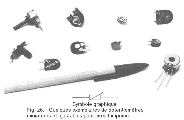
There are many miniature potentiometers, some of which are visible in Figure 26. Due to their small dimensions, these components are quite fragile and in most cases they are used as adjustable devices.
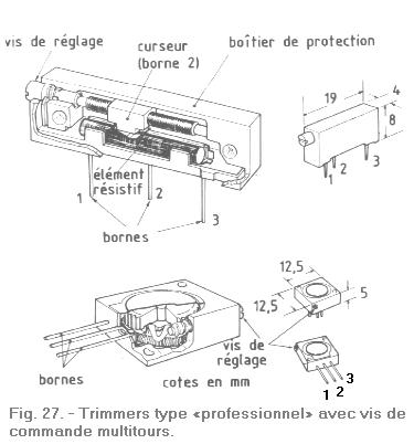
These adjustable potentiometers also called "trimmers" are often devoid of control axis and instead have a slot or a central screw which allows adjustment with a screwdriver.
Precision trimmers have a micrometric adjustment screw positioning the slider in a ratio of 1 / 1 to 30 / 1 (Figure 27). They are used mainly for professional type applications ; the resistive element is constituted either by a wire wound on an insulating support, or by a layer of graphite.
The adjustable graphite potentiometers can dissipate a power between 0.1 W and 1 W approximately ; those with higher power are made with resistive wire.
The choice in the field of potentiometers with resistive element with graphite layer is very vast as in that of potentiometers wound where the resistive element consists of a wire wound on a determined support on which a cursor moves.
Depending on the section, the amount of wire and the type of winding, we get potentiometers with different characteristics.
With potentiometers with graphite layer, one cannot achieve very low ohmic values as with the wound potentiometers whose resistive range extends from the ohm to 200 kΩ (seldom beyond).
The power dissipation does not exceed 2 W for the potentiometers with graphite layer whereas it commonly reaches between 2 W and 5 W for the wound potentiometers.
For special purposes, there are wire potentiometers, this time called rheostats, which dissipate from 50 to 100 Watts.
Like those in graphite, the wound potentiometers can be single or double, with single or separate control, with or without switch ; their external appearance resembles that of the graphite potentiometers apart from their dimensions which are proportional to the power that can be dissipated.
The Figure 28 illustrates some examples of medium size and commonly used in the electronics industry ; the resistive element and the mechanical parts are contained in a phenolic resin case with a closing metal base.
We have just seen the fixed and variable resistors which are the most used components and the simplest to examine in electronics.
In the next lesson, we will carefully look at another component as useful as the resistor and often associated with the latter in electronic assemblies : the capacitor.


 Practical notes on resistance
 Click here for the next lesson or in the summary provided.
 Top of page
 Next Page