An electrical or electronic circuit is realized by a set of pieces of different species with different functions and generally known as the "components".
These components are formed of resistors, capacitors, inductors, transformers, electronic tubes, semiconductors, integrated circuits, connection and switching materials.
The technician must know these components in order to use them in the best conditions.
1. - CLASSIFICATION OF RESISTANCES
Resistors are the most used components in circuits ; they have a resistance to the flow of current.
We find many types, different in their structure, their shape, their electrical characteristics according to the manufacturing technique and passed the job to which they are intended.
Resistances can be classified according to the model in Figure 1.
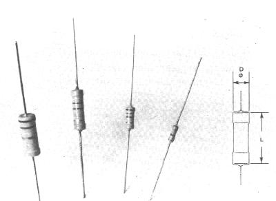
These resistors have a determined value and come in three types : agglomerated, coated and wound.
It is according to this model that the characteristics necessary for the realization of an assembly depend.
2. 1. - TECHNICAL DATA OF FIXED RESISTORS
The electrical resistivity is the nominal value in ohm (symbol Ω) at an ambient temperature of 25° C. High values are expressed in multiples of ohm.
The kilo-ohm (kW)
= 1 000 W
The mégohm (MW) = 1 000 000 W
The tolerance is a percentage, more and less around the nominal value, that the supplier undertakes to respect for all the parts delivered. It is understood for new parts before use, because thereafter variations may be greater after prolonged operation.
The tighter the tolerance, the better the precision ; if we take a resistor with a nominal value of 120 Ω with a tolerance of ± 10%, we have a deviation of ± 12 Ω (120 x ± 10 / 100 = ± 12).
The resistance can then have a real value between a minimum of 108 Ω (120 - 12 = 108) and a maximum of 132 Ω (120 + 12 = 132). If this time the tolerance is only 2%, this time we have a deviation of ± 2.4 Ω (120 x ± 2 / 100 = ± 2.4) ; the actual value is between a minimum of 117.6 Ω (120 - 2.4 = 117.6) and a maximum of 122.4 Ω (120 + 2.4 = 122.4).
The nominal power is the power which the resistance in calm air can dissipate at normal atmospheric pressure and for an ambient temperature generally of 20 or 25° C. It is determined so that under these conditions no point of resistance exceeds the temperature set for this type of manufacturing.
If the ambient temperature is higher, the admissible power must be reduced in order to stay within the temperature limits of the resistance. Reduction curves are established for each of the models.
** The temperature coefficient
is the quotient of the relative change in resistance by the change in temperature. It is expressed in part per million per centigrade degree (ppm / °C). For common resistors, the temperature coefficient is between 50 ppm / °C and 100 ppm / °C.
For example, a resistance of 2 000 Ω at 20 °C with a temperature coefficient of 80 ppm / °C increases its value by 0.16 Ω for each increase in temperature by 1° C:
2 000 x 80 / 1 000 000 = 0,16 W/°C
In an ambient environment at a temperature of 60° C, the resistance takes a value of 2 006.4 Ω (0.16 Ω / °C x 40 °C = 6.4 Ω). For negative temperature coefficients, the resistance value decreases as the temperature increases.
The maximum terminal voltage. The voltage across a resistor is given by the formula :
U in volts, P
in watts (this is the nominal power of the resistor), R in ohms.
Without overloading the resistance in power, very high voltages are obtained at the terminals, for high ohmic values. However, as a result of the dielectric strength of the materials used, one should not exceed a voltage, generally lower, fixed by the numbers. It is therefore the voltage at the terminals which limits the admissible power at this time.
** The Stability It is said that a resistance is stable, when after a long use, its value remains close to that which it had originally. This change in value depends on the type and technology of manufacturing. Wirewound or metallic film resistors are very stable, agglomerated resistors are less so.
** The voltage coefficient is the measure of the variation of the resistance value as a function of the voltage across its terminals. It is expressed as a percentage change per volt. The voltage coefficient is negligible for wirewound resistors and metal layer resistors. It is appreciable for agglomerated resistances (0.02% V).
** The noise voltage All the resistors produce at the terminals a parasitic voltage produced by the thermal agitation of the molecules. This voltage is very low for wire-wound and metal film resistors, it is higher for agglomerated resistors, because there is added a noise voltage caused by the flow of current in a heterogeneous material.
It is measured in microvolts per volts applied to the terminals (µV / V). It limits the possibility of amplification of the devices, because at a certain level, it becomes annoying.
This noise is mainly composed of low frequencies below 10 kHz, therefore audible, and it increases with the ohmic value of the resistance.
2. 2. - TECHNIQUE
OF MANUFACTURE OF FIXED RESISTORS
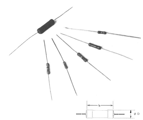
The agglomerated resistors consist of a mixture of carbon, insulating material and binder. The body of these resistors in which the two terminals are installed (connection wires) is protected by an envelope of insulating material (Figure 2-a).
The percentage of carbon makes it possible to determine the value of the resistance for the given dimensions. The more carbon there is, the less the resistance to a high resistance value.
A more recent manufacturing technique consists in depositing the resistive carbon and binder mixture in the form of a layer around a small special glass tube in which the two terminals are threaded in contact with the resistive material. The resistance thus formed is coated in a thermosetting insulating plastic resin (Figure 2-b).
The terminals inserted deep into the glass support allow better thermal conduction, hence better heat dissipation.
The normalized values of commercially available agglomerated resistors range from 1 Ω to 22 MΩ with tolerances of ± 5%, ± 10% and ± 20%. One finds the following powers : 1 / 8 W, 1 / 4 W, 1 / 2 W, 1 W, 2 W, 3 W and 4 W whose dimensions vary proportionally (Figure 2-c).
The power and the ohmic value of a resistor must appear in clear next to the electrical symbol of this one.
However, certain manufacturers reserve the right, in the design of the diagrams, to adopt graphic symbols which will be interpreted if necessary, according to the indications provided.
Particularly suitable for everyday use, agglomerated resistors whose cost price is low, are widely used in electronic circuits ; they have good mechanical strength, a low temperature coefficient in normal ambient conditions (below 60 °C) and good behavior at high frequencies (negligible parasitic inductance). On the other hand, due to their heterogeneous resistive element, they may have too high a noise voltage and insufficient stability for certain uses.
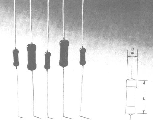
The film resistors also called film resistances are produced by various techniques; one of them consists of depositing by cracking (deposition by high temperature chemical process) on a central support made of insulating material (ceramic) a thin layer of carbon or tin oxide or of another material resistive.
The ohmic value depends on the thickness of the deposited layer and the substance used. However, it has been observed that the very thin layers, required by the high values, are fragile and unstable. Thus, a layer of 1 µm gives a temperature coefficient of - 180 ppm / °C, while a layer of 1 / 1000 µm has a temperature coefficient of - 1800 ppm / °C, that is to say ten times higher.
This is why one prefers to choose a layer a little thicker and to increase its length by tracing a spiral on the tube (Figure 3-a).
It is obvious that the finer the pitch of the net, the longer and narrower the resistive strip ; its resistivity also increases.
The spiraling is carried out on a special lathe by a diamond wheel. The lathe stops automatically when the desired ohmic value is obtained thanks to a measuring bridge. The accuracy is between ± 2% and ± 5%.
Another manufacturing method, better suited to obtain low resistance values, consists of depositing on a support in the form of a tube or wafer resistive metallic materials (alloys, noble metals or oxides) by vaporization under vacuum and in the form of layers. successively extremely thin until obtaining the thickness which gives the desired ohmic value (Figure 3-b).
With a metallic film deposit on a ceramic support, resistances with low ohmic values and greater heat dissipation are produced (from 0.07 Ω to 4 Ω for 1 W and from 0.1 Ω to 100 Ω for 14 W ) ; the absence of spiraling and therefore of inductance (self) allows their use in high frequency.
Whichever method is used, the deposited material ends in two terminals made of tinned copper wire, fixed by two metal cups or welded on the two ends of the resistive body. The whole is protected by a plastic varnish, a coating in synthetic resin or a molded coating which makes that externally these resistances resemble the current agglomerated resistances (Figure 3-c).
The multiple varieties of manufacturing methods for resistors and types of film adopted by manufacturers as well as the direct correlation between power and dimensions mean that the resistors have quite different electrical characteristics, while having the same external appearance.
Carbon layer resistors whose nominal value ranges from 1 Ω to 22 MΩ with typical tolerances of ± 5% or ± 10%, have a temperature coefficient between 150 and 800 ppm / °C, and, an admissible power going from 1 / 20 W to 2 W. They are used for general use.
They have high reliability and good behavior at high frequencies. In addition, they have low noise and are of moderate cost. They are in many ways comparable to agglomerated resistors.
The table in Figure 4 shows, by way of example, the main characteristics of the carbon film resistors from Philips and the dimensions relative to the admissible power at ambient temperature Ta = 70 °C.
Power (Ta = 70° C) W
Range of resistance values
Tolerances ± %
Max applicable voltage Veff
Dimensions x L in mm
0,2
10 W
- 220 kW
5
150
1,6 x 4
0,2
270 W
- 1 MW
10
150
1,6 x 4
0,2
10 W
- 220 kW
5
150
1,6 x 4
0,2
270 W
- 1 MW
10
150
1,6 x 4
0,33
1 W
- 1 MW
5
150
2,5 x 6,5
0,33
1,2 MW
- 10 MW
10
150
2,5 x 6,5
0,33
1
W
- 1 MW
5
150
2,5 x 6,5
0,33
1,2 MW
- 10 MW
10
150
2,5 x 6,5
0,5
1 W
- 1 MW
5
350
9,7 x 10
0,5
1,2 MW
- 10 MW
10
350
9,7 x 10
0,5
1 W
- 1 MW
5
350
9,7 x 10
0,5
1,2 MW
- 10 MW
10
350
9,7 x 10
0,67
1 W
- 1 MW
5
500
5,2 x 16,5
1,15
1 W
- 1 MW
5
750
6,8 x 18
2
10 W
- 1 MW
5
1 000
9 x 31,7
Fig. 4. -
Electrical characteristics and dimensions of carbon film resistors produced by Philips.
The metallic film resistors are used for professional uses, where are required : precision (tolerances less than or equal to 0.1%), the temperature coefficient close to ± 25 ppm / °C, high stability and low noise.
Naturally, the electrical characteristics can vary from one type of resistance to another depending on the specifications of use.
The table in Figure 5 summarizes the technical data and the dimensions of the metal film resistors from Philips and constitutes a comparison element with the carbon film resistors seen previously.
Power (Ta = 70° C) W
Range of resistance values
Tolerances ± %
Max applicable voltage Veff
Temperature coefficient ± ppm/°C
Dimensions D x L in mm
0,4
4,99 W
- 681 kW
0,5
250
50 *
2,5 x 6,5
0,4
4,99 W
- 681 kW
1
250
50 *
2,5 x 6,5
0,4
1 W
- 680 kW
2
250
100
2,5 x 6,5
0,4
1 W
- 680 kW
5
250
200
2,5 x 6,5
0,5
4,99 W
- 1 MW
0,5
350
50 *
3 x10
0,5
4,99 W
- 1 MW
1
350
50 *
3 x 10
0,5
5,1 W
- 1 MW
2
350
100
3 x 10
0,5
5,1 W
- 1 MW
5
350
200
3 x 10
0, 75
4,99 W
- 1 MW
1
500
100
5,2 x 16,5
1,6
10 W
- 10 kW
5
500
500
3,7 x 10
2,5
10 W
- 27 kW
5
500
500
5,2 x 16,7
* For values ≤
(less than or equal) 49,9 W
: 100 ppm/°C
Fig. 5. -
Electrical characteristics and dimensions of metal film resistors (general use) from Philips.
Metal oxide film resistors, the resistive element of which consists of tin oxide heated to 800° and sprayed onto the support, are characterized by a tolerance of ± 1%, a very low noise level, high stability and good operation at high frequencies ; their job is particularly professional.
"Metal-glass" film resistors have the resistive element obtained by coating an insulating support with precious metal powder such as silver and palladium, mixed with sprayed glass.
Although these resistors do not have the same precision as those with metallic film, they still exhibit great stability, low noise and above all great immunity to atmospheric agents ; they also withstand high temperatures and heavy overloads without damage. With the same spiraling method adopted for the carbon layer resistors and by moving the adjacent turns further apart, resistors supporting high voltages are produced : the electric arc being less stressed between two turns.
The Figure 6 gives some data on these resistances.
Maximum voltage value
Range of resistance values
Tolerance ± %
Power (Ta = 25°C)
W
Temperature coefficient ± ppm/°C
Dimensions D x L in mm
Vcc 3 500, Veff 2 500
1 MW - 33 MW
1 at 5
0,5
200
3,7 x 10
Vcc 10 000, Veff 7 000
1 MW - 68 MW
1 at 5
1
200
6,8 x 18
Fig. 6. - Electronic characteristics and dimensions of metal-glass resistors from Philips
The coiled resistances are obtained by winding a high resistivity wire (for example : nickel-chromium, constantan, manganine) on an insulating ceramic support impregnated, at high temperature, with special resins. The manufacturing techniques adopted for these resistances are also very variable so that one can generalize their shape and their dimensions.
On the Figure 7-a is represented a type of wound resistance obtained by winding a resistive wire around a raw and insulating support, little sensitive to the high temperatures ; the ends of the wire are soldered to the terminals and the assembly and protected with a cylindrical coating of molded plastic material, withstanding a temperature of 220 °C.
This type of coiled resistor therefore looks similar to that of an ordinary agglomerated resistor, with the difference that the first colored ring is twice the others. The power of these resistors does not generally exceed 2 Watts and the values range from 1 Ω to 10 Ω.
The wound resistance illustrated in the Figure 7-b differs from the previous one by the external insulating coating which can support a temperature of 350 °C. The ohmic values of these resistors range from 0.1 Ω to 33 kΩ with a maximum power of 30 Watts for everyday use.
In the Figure 7-c, this type of coiled resistors is particularly adapted to dissipate high powers ; they are made with a square section soapstone envelope and sealed with a special cement.
In Figure 8 are illustrated some examples of these resistors, some of which are provided with a steel spring acting as a cooling fin. In this way, the calories are removed more and the nominal power dissipated by the resistance can be increased. This spring also constitutes a member of fixing to the chassis and sometimes it forms integral part of the resistance (Figure 8-b).
There are also some types of resistors provided with a delayed thermal protection device, constituted by a spring strip welded with tin on one of the terminals (Figure 8-c) ; if the temperature of the resistor exceeds a fixed threshold, due to a fault on the circuit, the tin melts, releasing the end of the strip which expands outwards and removes the electrical connection, thus protecting the circuit subsequent damage. When the fault on the circuit is detected, we can fix the strip to the terminal of the resistor, simply by soldering with tin. (In principle, it should even be replaced, because the latter undergoes heating).
Other types of wirewound resistors are illustrated in Figure 9 ; these are copies provided with one or more intermediate sockets and therefore suitable for use as resistive dividing bridges.
They are manufactured with ohmic values and various powers which can reach for the latter from 8 to 250 Watts.
Isolation is achieved by a special vitreous enamel. The ceramic support with circular section (sometimes elliptical to reduce its size) is porous to promote cooling.
In the measuring instruments, resistors are used whose nominal value is less than the ohm, the very high precision and the maximum power of a few Watts ; the resistant wire is wound on a mandrel that is not very sensitive to heat (Figure 10).
The two terminals of the mandrel, to which the ends of the resistive winding are fixed, can be connected to the electronic circuit by soldering with tin.
These wirewound resistors are available over a wide range of values from a few tenths of an ohm to 100 kΩ with tolerances on the order of ± 10%, ± 5% and even ± 0.5% for the most precise. They are used when those of the agglomerated carbon type are not suitable : for a high dissipation, a narrow tolerance and above all for a great stability of the ohmic value.
The noise voltage of these resistors is generally negligible but we avoid using them in circuits where the frequency is higher than the audio band because of their high residual inductance.


 Fixed resistors
 Click here for the next lesson or in the summary provided.
 Top of page
 Next Page