 The Multiplexers The Multiplexers |
Footer |
Binary Comparators - Multiplexers :
2. - BINARY COMPARATORS
A binary comparator is a logic circuit that compares two binary numbers generally denoted A and B.
It has 3 outputs denoted by A = B, A > B et A < B which indicate the result of the comparison as follows :
![]() If the number A
is equal to the number
B (A = B), the output A = B goes to state
1 while the outputs A
> B and A < B go to state
0.
If the number A
is equal to the number
B (A = B), the output A = B goes to state
1 while the outputs A
> B and A < B go to state
0.
![]() If the number A
is strictly greater than the number B,
only the output A > B goes to state
1.
If the number A
is strictly greater than the number B,
only the output A > B goes to state
1.
![]() If the number A
is strictly less than the number B,
only the output A < B goes to state
1.
If the number A
is strictly less than the number B,
only the output A < B goes to state
1.
We will see how to make a comparator of two binary digits using logic gates.
2. 1. - COMPARATOR OF TWO BINARY DIGITS
Or to compare the two binary digits A and B. Let us examine the cases where A = b, A > B and A < B.
![]() The two numbers A and B are equal if A = B = 1 or A = B = 0. The output A = B must therefore go to state 1 only for these two combinations. His equation is therefore A . B
+
The two numbers A and B are equal if A = B = 1 or A = B = 0. The output A = B must therefore go to state 1 only for these two combinations. His equation is therefore A . B
+ ![]() .
. ![]() .
.
![]() The number A is strictly greater than the number B only if A = 1 and
B = 0. The output
A > B
must therefore go to state 1 only for this combination. His equation is A
The number A is strictly greater than the number B only if A = 1 and
B = 0. The output
A > B
must therefore go to state 1 only for this combination. His equation is A![]() .
.
![]() The number A is strictly less than the number B only if A = 0
et B = 1. The output
A < B
must therefore go to state 1
only for this combination. Its equation
The number A is strictly less than the number B only if A = 0
et B = 1. The output
A < B
must therefore go to state 1
only for this combination. Its equation ![]() B.
B.
All these considerations are reflected in the truth table of Figure 19.
Consider the equation of the output A
= B, AB + ![]()
![]() .
.
We know that AB + ![]()
![]() + A
+ A![]() +
+ ![]() B
= 1 because whatever the states of A and B, one of the four combinations is worth 1.
B
= 1 because whatever the states of A and B, one of the four combinations is worth 1.
We deduce that AB + ![]()
![]() is the logical complement of A
is the logical complement of A![]() +
+ ![]() B
since the logical sum of these two expressions is 1.
B
since the logical sum of these two expressions is 1.
So, AB + ![]()
![]() = A
= A![]() +
+ ![]() B.
B.
We are thus led to the logic diagram of Figure 20 which provides the three signals A < B, A = B and A > B from bits A and B.
2. 2. - ANALYSIS OF AN INTEGRATED COMPARATOR : THE 7485
The integrated circuit 7485 is a 4 bits comparator, that is, it compares two 4 bits numbers.
In addition, it has 3 entries A = B, A > B and A < B which allow the cascading of several comparator circuits of the same type.
Thus, we can compare numbers of 8, 12, 16 bits ...
The pinout of this circuit is given in Figure 21, while Figure 22 shows its logic diagram.
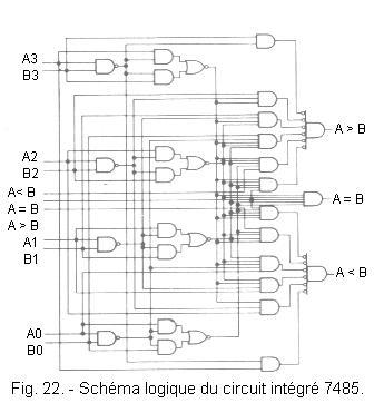
With this circuit, the number A composed of the bits A3, A2, A1 and A0 (A3 = MSB and A0 = LSB) is compared with the number B composed of the bits B3, B2, B1 and B0 (B3 = MSB and B0 = LSB).
The truth table in Figure 23 highlights the action of the inputs A > B, A < B and A = B.
![]() If it is desired that the output A = B goes to state 1 each time the two binary numbers are equal, it suffices to bring the input A = B to state 1, the state of the inputs A < B and A > B then not important.
If it is desired that the output A = B goes to state 1 each time the two binary numbers are equal, it suffices to bring the input A = B to state 1, the state of the inputs A < B and A > B then not important.
![]() If it is desired that the output A > B goes to state 1 also in the case where the two binary numbers are equal, it suffices to bring the input A > B to the state 1 and to carry the inputs A < B and A = B at 0.
If it is desired that the output A > B goes to state 1 also in the case where the two binary numbers are equal, it suffices to bring the input A > B to the state 1 and to carry the inputs A < B and A = B at 0.
In this configuration of the state of the inputs A > B, A < B and A = B, the output A > B is in the state 1 when the binary number A is greater than the binary number B or when these two numbers are equal. It indicates if A ³ B.
![]() Similarly, by setting input A
< B to state 1 and inputs A > B and
A = B
to state 0, the output A < B indicates the binary number A
is less than or equal to the binary number B.
Similarly, by setting input A
< B to state 1 and inputs A > B and
A = B
to state 0, the output A < B indicates the binary number A
is less than or equal to the binary number B.
By putting two comparators 7485 in series, two numbers of 8 bits can be compared. Just connect the output A = B of the first comparator to the corresponding input of the second and do the same with the outputs A > B and A < B. The links to be made are shown in Figure 24.
Thus, the number A formed of the 8 bits A7 to A0 (A7 = MSB and A0 = LSB) and the number B formed of the 8 bits B7 to B0 (B7 = MSB and B0 = LSB) are compared.
The first circuit compares the low weights of A with the low weight of B. The result of this comparison is transmitted to the inputs A < B, A = B and A > B of the second circuit.
This one compares the strongest of A with the highs of B and, according to the result of the comparison of the low-order bits of A et B, indicates on its outputs A > B, A = B and A < B the result of the comparison of the numbers A and B.
![]() 3. - THE MULTIPLEXERS
3. - THE MULTIPLEXERS
In this chapter, we will examine logic circuits that are widely used to refer data : multiplexers.
These circuits have several data inputs and a single output.
Using one or more control inputs, one of the data inputs is routed to the output. The output «copies» the selected input.
A multiplexer can be compared to a mechanical switch. The number of data inputs of a multiplexer defines the number of channels of a multiplexer. If a multiplexer has n data inputs, it is said to be an n channel multiplexer.
The number of control inputs is a function of the number of channels of the multiplexer. For example, for a 4-channel multiplexer, 2 control inputs are needed. Indeed, with 2 control inputs, one can form 22 = 4 distinct logical combinations to differentiate the 4 channels of the multiplexer. An 8 channel multiplexer would require 3 command inputs since 23 = 8.
Let's look at the simplest multiplexer, the two-way.
3. 1. - THE MULTIPLEXER WITH TWO WAYS
Figure 25 shows the symbolic scheme and the mechanical equivalent of a 2-channel multiplexer.
Depending on the state of the selection input A, the output S copies either the input D0 or the input D1.
Suppose that for A = 0, S = D0 and that for A = 1, S = D1.
We deduce the following equation of S :
S = D0![]() + D1A
+ D1A
The combinational network of Figure 26 can provide the signal S.
3. 2. - ANALYSIS OF A TWO-CHANNEL INTEGRATED MULTIPLEXER : THE 74157
The integrated circuit 74157 is a quadruple 2-channel multiplexer with common selection input. The validation input (STROBE), also common, forces the four outputs to L level when it is subjected to level H.
The pin assignment and logic diagram of this circuit are given in Figure 27.
The truth table in Figure 28 shows that the data Ai is transferred to Yi when the SELECT input is in the 0 state. When this input is in the 1 state, the Bi data is transferred to Yi.

Consider data A consisting of bits A1, A2, A3 and A4, data B consisting of bits B1, B2, B3 and B4 and data Y consisting of bits Y1, Y2, Y3 and Y4.
In normal operation, the STROBE input is kept at 0.
If the SELECT input is in the 0 state, the Y data is equal to the A data.
If the SELECT input is in state 1, the data Y is equal to the data B.
A multiplexer can therefore route data consisting of several bits.
3. 3. - THE FOUR-WAY MULTIPLEXER
Figure 29 shows the symbolic scheme and the mechanical equivalent of a 4-channel multiplexer.
The multiplexer has two control inputs A and B to select one of the four inputs D0, D1, D2 or D3.
In general, the selected input carries in index the state corresponding to the combination of the control inputs. This is reflected in the table of Figure 30.
From this table, we can extract the equation of the following S output :
S = ![]() .
. ![]() . D0 +
. D0 + ![]() . A . D1 + B .
. A . D1 + B . ![]() . D2 + B . A . D3
. D2 + B . A . D3
We arrive at the logic diagram of Figure 31.
.gif)
 Click here for the next lesson or in the summary provided for this purpose. Click here for the next lesson or in the summary provided for this purpose. |
 Top of page Top of page |
|
Previous Page |
 Next Page Next Page |
Nombre de pages vues, à partir de cette date : le 27 Décembre 2019

Envoyez un courrier électronique à Administrateur Web Société pour toute question ou remarque concernant ce site Web.
Version du site : 10. 4. 12 - Site optimisation 1280 x 1024 pixels - Faculté de Nanterre - Dernière modification : 02 Septembre 2016.
Ce site Web a été Créé le, 14 Mars 1999 et ayant Rénové, en Septembre 2016.