 The Demultiplexers
Analysis of a 4-Way Integrated Multiplexer ; the 74153 - Demultiplexers :
3. 4. - ANALYSIS OF AN INTEGRATED 4-WAY MULTIPLEXER : 74153 (Return to Practice N° 12)
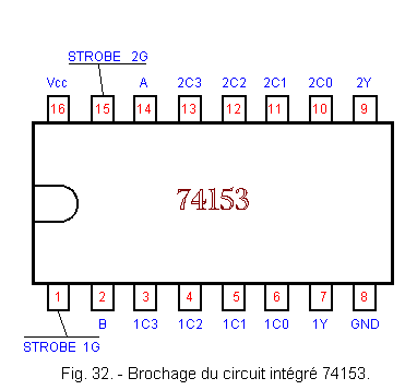
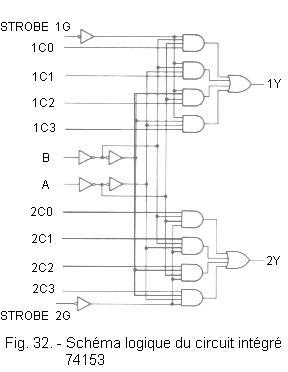
The integrated circuit 74153 contains two 4-way multiplexers with common A and B selection inputs. Each multiplexer has a validation input G (STROBE). This, brought to state 1, forces the output of the multiplexer corresponding to state 0 independently of the state of the other inputs.
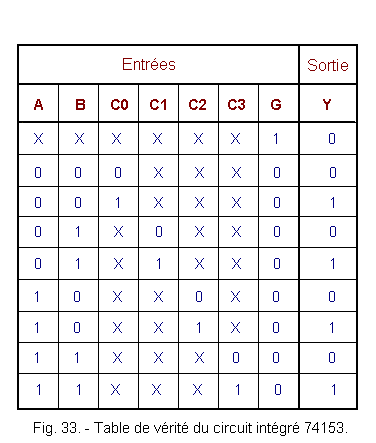
The pinout and the logic diagram of this integrated circuit are given in Figure 32, while Figure 33 gives its truth table.
3. 5. - USE OF A MULTIPLEXER AS A FUNCTION GENERATOR
In addition to switching multiple logical signals, the multiplexer can be used to replace a network.
This is made possible because the equation of the output of a multiplexer shows all possible combinations of the control inputs.
Take the example of a 16-channel multiplexer (E0 to E15), thus to 4 control inputs (A, B, C and D).
The output S to for the equation :
S = ![]()
![]()
![]()
![]() E0
+
E0
+ ![]()
![]()
![]() A
E1 + ... D C B A E15
A
E1 + ... D C B A E15
Since all the combinations of the inputs A, B, C and D are present in this equation, we can realize with this multiplexer any logical function having the same number of inputs, either 4.
The method is as follows :
![]() The control inputs of the multiplexer become the inputs of the network that one wants to realize.
The control inputs of the multiplexer become the inputs of the network that one wants to realize.
![]() To know how to position the other entries, we draw up a table with all the combinations of the command entries.
To know how to position the other entries, we draw up a table with all the combinations of the command entries.
![]() For each combination, we indicate the logical level that the output must take.
For each combination, we indicate the logical level that the output must take.
![]() The corresponding input is subjected to the combination of the control inputs at the desired output level.
The corresponding input is subjected to the combination of the control inputs at the desired output level.
The following example will clarify the procedure.
There are four switches that can be connected to either the supply voltage or to the ground and one wants to know if at least two switches are closed on the positive supply voltage.
A circuit of this kind can be used for signaling faults, or for the counting of parts on a production line.
If integrated logic gates are used, the circuit shown in Figure 34 is obtained.
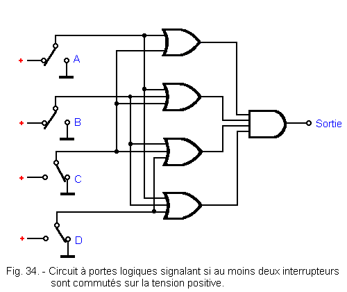
The output of the circuit goes to the H level when at least two of the inverters are switched to the positive voltage.
We notice that we have to use several types of doors, 3-input OR gates, 2-input OR gates and 4-input AND gates.
We will see that the same function can be achieved with a single multiplexer with sixteen inputs.
From what has been said before, the four switches are connected to the four control inputs D, C, B, A of the multiplexer.
To determine how to connect the sixteen data entries, simply follow the procedure described and construct a sixteen-line table like that in Figure 35.
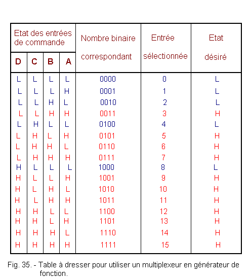
For each combination of control inputs, the state of the output must be reported in the output column.
In the table of Figure 35, the lines represented in red characters correspond to the case where two or more control inputs are at level H and for which the output must therefore be at level H.
It remains now to bring the selected entries to the levels indicated in the last column.
For example, the input 2 must be brought to the level L, thus connected to the ground. On the other hand, the input 3 is at the level H, thus connected to the positive voltage.
The resulting circuit is shown in Figure 36.
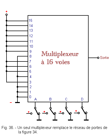
The advantage of the multiplexer compared to the door network is obvious : a single integrated circuit replaces the entire door network. This one indeed requires at least three integrated circuits : one for the AND and two for the OR.
In general, it is more economical to use complex integrated circuits such as the multiplexer instead of traditional doors (NAND, NOR, AND, OR ...) to perform the function of a combinational network.
In addition, the use of a multiplexer makes it easy to switch from one logic function to another by changing the level of the data inputs.
![]() 4. - THE DEMULTIPLEXERS
4. - THE DEMULTIPLEXERS
In this chapter, we will examine the demultiplexers which are circuits whose function is the inverse of that of the multiplexers.
Indeed, they have a single data entry and several outputs or «channels».
The information present on the data input is switched to the output selected by the state of the control inputs. Unselected outputs move to state 1.
Let's take a look at the simplest demultiplexer, the 2-way one.
4. 1. - THE TWO WAY DEMULTIPLEXER
The symbolic scheme and the mechanical equivalent of a 2-way demultiplexer are shown in Figure 37.
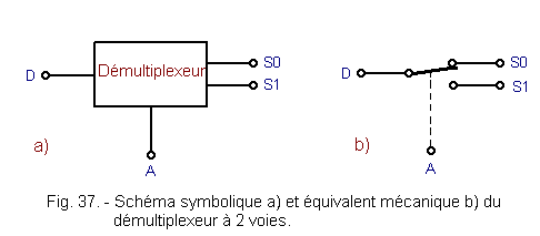
The data present in D is switched to S0 or S1 according to the state of the control input A.
In general for A = 0, the output S0 is selected and for A = 1 it is the output S1 ; the unselected output being in state 1.
The combinational circuit that performs the function of the 2-way demultiplexer must therefore correspond to the truth table of Figure 38.
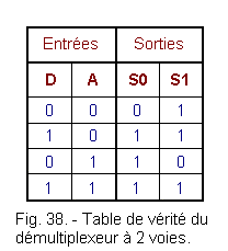
From this table, we immediately deduce that S0 = A + D.
To find the simplest equation of S1, let us draw up Karnaugh's table (Figure 39).
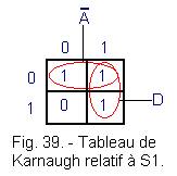
The two groups ![]() and
D give us the following equation of S1 :
and
D give us the following equation of S1 :
S1 = ![]() + D
+ D
If we wish to realize the combinatory circuit with NAND gates, we must transform the expressions A + D and ![]() + D with the help of the theorem of DE Morgan :
+ D with the help of the theorem of DE Morgan :
.gif)
The expressions ![]() and
and
![]() lead us to the logic diagram of figure 40.
lead us to the logic diagram of figure 40.
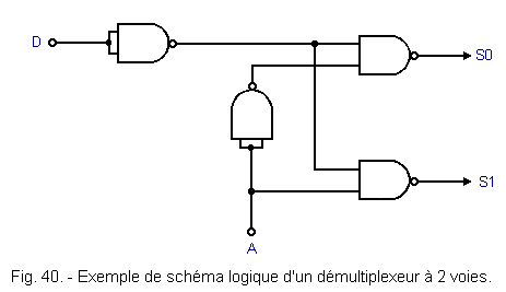
There is no built-in 2-way demultiplexer. If the integrated circuit 7400 is available, the circuit of Figure 40 can be realized.
Otherwise, turn to the 4-way integrated demultiplexer 74LS139.
4. 2. - ANALYSIS OF A FOUR-WAY INTEGRATED DEMULTIPLEXER : THE 74LS139
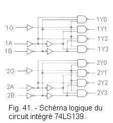
The 74LS139 integrated circuit contains two 4-way demultiplexers. Each of them has 2 selection inputs A and B, a data input G and 4 outputs (Y0 to Y3).
The pinout and logic diagram of this circuit are given in Figure 41, while Figure 42 gives its truth table.
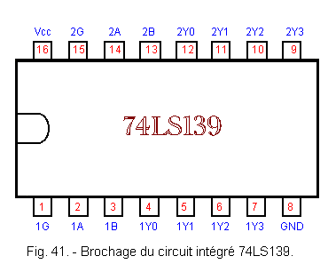
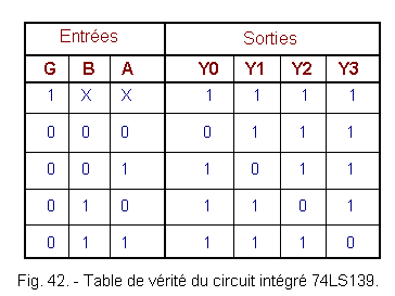
Note that the binary number formed by the state of the selection inputs B and A gives the decimal index of the output concerned.
For example, when BA = 10 (is 2 in decimal), the output concerned is Y2.
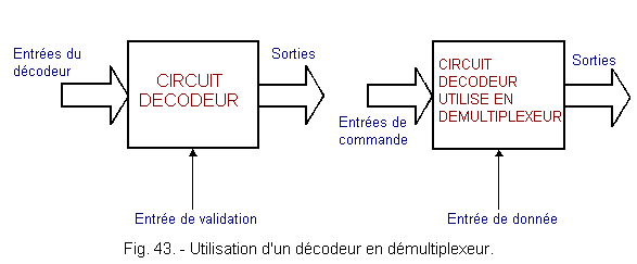
![]() 4. 3. - USE OF A DECODER IN DEMULTIPLEXER
4. 3. - USE OF A DECODER IN DEMULTIPLEXER
We know that most decoders have their active outputs in state 0 and their enable input active in state 0.
Let the validation input be in state 0 : the decoder is enabled, and the output selected by the decoder inputs goes to state 0.
We can say that the data «0» present on the validation input is transferred to the selected output.
Let us now take the validation input to state 1 : the decoder is invalid and all its outputs go to state 1, in particular the output selected by the decoder inputs. Similarly, we can say that the data «1» present on the validation input is transferred to the selected output.
In summary, the logic data present on the validation input is switched to the output selected by the inputs of the decoder.
Thus, to use a demultiplexer decoder, the validation input becomes the data input and the decoder inputs become the control inputs of the demultiplexer.
Figure 43 illustrates how one goes from a decoder to a demultiplexer.
The next theory will deal with memories.
 Click here for the next lesson or in the summary provided for this purpose Click here for the next lesson or in the summary provided for this purpose |
 Top of page Top of page |
|
Previous Page |
 Next Page Next Page |
Nombre de pages vues, à partir de cette date : le 27 Décembre 2019

Envoyez un courrier électronique à Administrateur Web Société pour toute question ou remarque concernant ce site Web.
Version du site : 10. 4. 12 - Site optimisation 1280 x 1024 pixels - Faculté de Nanterre - Dernière modification : 02 Septembre 2016.
Ce site Web a été Créé le, 14 Mars 1999 et ayant Rénové, en Septembre 2016.