In the series of multiplier of tension, one also meets quite often, the assembly TRIPLEUR OF VOLTAGE.
The diagram of this one is represented figure 31.
Again, it must be remembered that point B is grounded, sets the zero reference level (zero potential).
However, from the alternative point of view, when the point A is negative (-100 Volts for example), the point B is positive with respect to A.
After this reminder, let's see how the circuit works.
a) During the negative alternation (Figure 31).
Since the anodes of the rectifiers D2 and D3 are negative, these components are thus blocked.
On the other hand, since the anode of D1 is positive with respect to its cathode, this component drives and charges C1 at the peak value of the sector.
Note the polarity at point B and at the terminals of C1.
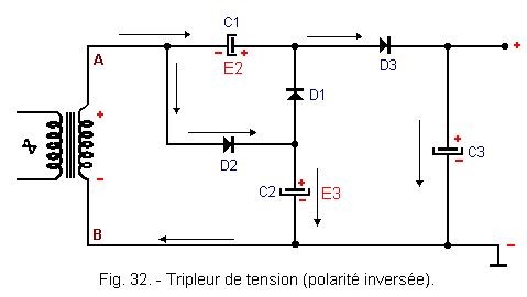
b) During positive alternation (Figure 32).
The rectifier D1 is blocked. On the other hand, D2 and D3 lead.
We then have :
1) - D2 charging the capacitor C2 to the peak value of the sector (E3).
2) -D3 charging the capacitor C3 to the value of E2 + E3, that is to say 3 E1.
The empty output voltage is therefore 4.23 x U eff (three times the peak value).
With a normal load, the output voltage is of the order of 3.2 x U eff.
Peak reverse voltage remains at 2.82 x U eff for each rectifier.
Indeed, even for D3, which apparently supports the most important reverse voltage, we have, when this rectifier is blocked :
- Cathode of D3 = + 4.23 x U eff.
- Anode of D3 = + E1 (voltage across C1), see + 1.41 x U eff.
Reverse voltage on D3 = 4.23 - 1.41 = 2.82 x U eff.
For D1 blocked, we have :
- Cathode of D1 = + 4.23 x U eff.
- Anode of D1 = + E3 (voltage at the terminals of C2) is + 1.41 x U eff.
Reverse voltage on D1 = 4.23 - 1.41 = 2.82 x U eff.
And finally, for blocked D2, we have :
- Cathode of D2 = - 1.41 x U eff.
- Anode of D2 = + 1.41.
Reverse voltage on D2 = 1.41 + 1.41 = 2.82 x U eff.
As for the capacitors, it is obvious that C3 supports a maximum voltage of 4.23 x U eff, but C1 and C2 only support the maximum voltage, due to an alternating load, that is to say 1.41 x U eff.
The principle of charging a capacitor through a rectifier during an alternation and adding to it the maximum voltage of the source during the other alternation, can be applied to an unlimited number of elements.
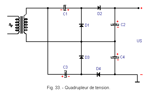
Thus, by putting the output voltages of two doublers in series, we arrive at the VOLTAGE QUADRUPLE (Figure 33).
It is easy to see on the diagram that it is about two doublers of SCHENKEL in series.
The operating principle is now well known and we will not dwell on this topic anymore.
Note however that for the various types of voltage multipliers, the DC output voltage (unladen) is always equal to :
US = 1,41 x U eff x k
With k = multiplication factor (k = 2 for a doubler, 3 for a tripler, 4 for a quadrupleur, etc ...).
As for the reverse voltage supported by each rectifier, it always remains 2.82 x U eff.
Example for the voltage quadruple..
If the secondary voltage is 100 Volts (50 Hz), we will have :
US = 1,41 x 100 x 4 = 564 Volts.
Reverse voltage:2,82 x 100 = 282 Volts.
It should also be noted that in all cases, with a normal load, the DC voltage available is substantially equal to :
U eff x k
With k = multiplication factor (k = 2 for a doubler, 3 for a tripler, 4 for a quadrupleur, etc ...).
Thus, with the quadruplier circuit of the preceding assembly, the DC output voltage, in the presence of a normal load, will be :
U eff x k = 100 x 4 = 400 Volts
Capacitors C1 and C3 only support a voltage of 1.41 x U eff, while capacitors C2 and C4 obviously support a voltage of 2.82 x U eff.
The capacitive value of these components is of the order of 100 µF.
All capacitive values given from the voltage doubling circuit are valid only when the circuits are equipped with solid-state rectifiers.
In the case of use of vacuum diode, can not, as the semiconductor diodes, provide an instantaneous flow, much larger than the average flow, the capacitive values are lower.
This remark has only a theoretical interest, because in practice, we can consider that all electronic power supplies for small and medium powers (that is to say, all power supplies for purely electronic devices), are equipped with solid state rectifiers.
Note finally that it is extremely rare for this kind of power supply, to find circuits exceeding the quadrupling of the voltage.
In practice, we can even say that the doubling of voltage (LATOUR doubler in principle) is the only one commonly used.
On the other hand, for the very small powers (about ten mA), one meets quite often the assembly tripler and quadrupleur.
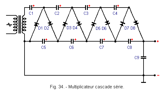
Finally, when it is necessary to have a very high voltage (several thousand volts), under a very low flow (a few mA), it is possible to push the charging principle of the capacitors even further and to achieve multiplication circuits cascade.
The first type of this kind of editing is called the cascade serial multiplier (Figure 34).
The first two rectifiers D1 and D2, with capacitor C1 form a SCHENKEL doubler, charging C5 at twice the peak voltage of the secondary.
D3 and D4 with C2, constitute the second doubler, charging C6 and so on.
The chain comprising a total of four voltage doublers in series, is output as a voltage eight times higher than the sector peak voltage.
Example : If the secondary delivers a voltage of 250 volts eff, a peak value of 250 x 1.41 = 352.5 volts, the DC output voltage (no load) is :
352,5 x 8 = 2 820 Volts (if mounting, be very careful).
It should be noted that the capacitors only have to withstand a voltage of 2.82 x U eff, except C1 (1.41 x U eff) and C9, for which the applied voltage depends on the number of rectifiers.
In the case of the mounting of Figure 34, C9 supports a voltage of 2820 volts.
As for the rectifiers, the peak reverse voltage remains of 2.82 x U eff for each of these components.
Indeed, by examining for example the circuit relating to D8, which apparently has to withstand a higher voltage than that applied to D1, it is found that due to the presence of C4, the anode of D8 remains positive during the negative half cycle of tension.
The maximum potential difference between the cathode and the anode of each rectifier therefore remains equal to 2.82 x U eff.
A very simple calculation makes it possible to make sure of it :
Between the positive terminal of C5 and the mass (output of the first doubler), the DC voltage is :
(250 x 1,41) x 2 = 705 Volts.
Between the positive terminal of C6 and the earth (output of the second doubler), the DC voltage is :
705 x 2 = 1 410 Volts.
However, the potential difference between the + terminal of + C5 and the terminal of C6 remains :
1 410 - 705 = 705 Volts,
that is to say U eff x 2,82.
In this type of assembly, the current in play is always very low (a few mA). As a result, the capacitive value of the capacitors is small compared with previous assemblies.
For these, we had values of the order of a hundred microfarads, which involved the use of electrochemical capacitors.
For the cascade voltage multipliers, the capacitive values are of the order of a few microfarads at most. It is therefore possible to use ordinary capacitors (paper type or similar).
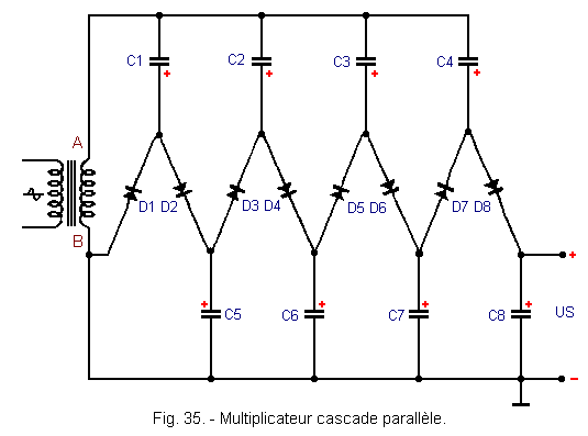
Of a less common use than the serial cascade multiplier, however, we sometimes find the parallel cascade multiplier (Figure 35).
The operation of this circuit differs from the previous one.
Indeed, the capacitors C1, C3, C5 and C7 are in parallel, as well as the capacitors C2, C4, C6 and C8.
Therefore, after a full period of the voltage, C2 supports a voltage of 2.82 x U eff.
This voltage, to which is added the peak value of the sector, when the point B is positive, gives to the terminals of C3 a voltage of 2.82 x U eff + 1.41 x U eff.
When point A is negative, this voltage is :
2,82 x U eff + 1,41 x U eff = 4,23 x U eff
gives at the terminals of C4 a value of 4.23 x U eff + 1.41 x U eff (from C3) or 5.64 x U eff and so on.
As a result, the voltage supported by each capacitor increases with the progression of the rise of the DC voltage along the chain.
We have :
C1 = 1,41 x U eff
C2 = 2,82 x U eff
C3 = 4,23 x U eff
C4 = 5,64 x U eff
The capacitor isolation voltage must of course follow this progression.
As for the reverse voltage supported by the rectifiers, it remains 2.82 x U eff.
Indeed, for D4 for example, we have a voltage of 5.64 x U eff on the cathode (voltage across C4) and a voltage of 4.23 x U eff on the anode (voltage across C3).
The difference is therefore :
5,64 - 4,23 = 1,41 x U eff
And to this one is added the value of peak, when D4 is blocked, a reverse voltage of peak of :
1,41 + 1,41 = 2,82 x U eff
As in the previous case, the DC output voltage at no load (voltage across C8) is, with a secondary delivering 250 U eff, is :
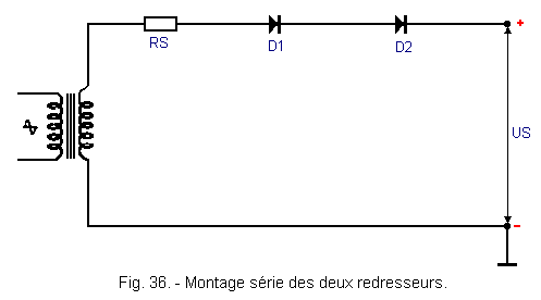
In order to increase the value of the reverse voltage, which can be supported without damage by the rectifiers, it is conceivable to mount them in series, thus straightening higher voltages.
Many manufacturers use this solution. The circuit is then as shown in Figure 36.
This circuit is only feasible in the case where the two rectifiers are identical in terms of direct and inverse resistance.
In fact, in the opposite case, there is at the terminals of each rectifier, a voltage proportional to the inverse of the current, the inverse circulating in them.
Let's take a simple example.
If the secondary supplies a voltage of 100 Volts eff, the maximum reverse voltage may have the value :
100 x 2,82 = 282 Volts
Starting from this calculation, we will choose rectifiers capable of supporting each 282 / 2 = 141 Volts (the rectifiers are in series, each component only supports half of the maximum reverse voltage).
Now, if D1 has an inverse resistance equal to twice that of D2, the effective voltage across D1 will be twice that applied to D2.
Thus, the voltage across D1 will be 66.6 volts and the voltage across D2 will be 33.3 volts.
For D1, the reverse voltage will therefore be : 66.6 x 2.82 = about 188 volts.
For D2, it will be : 33.3 x 2.82 = about 94 volts.
It is easy to understand that D1 (designed for a reverse voltage of 141 Volts) will not withstand the applied voltage for a long time (188 Volts).
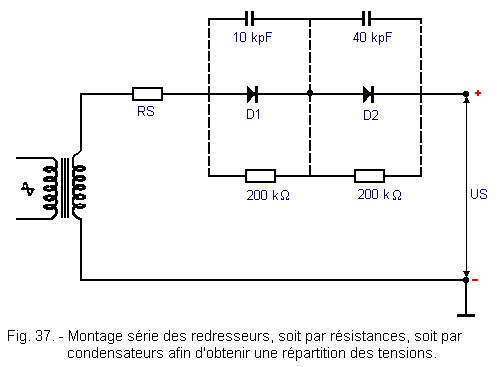
Since it is very rare to find two rectifiers with the same direct and inverse resistance, it is necessary to provide a circuit to ensure equal distribution of voltages.
For that, it is enough to shunt each rectifier, either by a capacitor of approximately 10 kpF, or by a resistance of 150 to 220 kΩ.
Either of these elements having a low impedance compared to the inverse resistance of the rectifiers, will be able to ensure a substantially equal distribution of voltages.
On the other hand, the high impedance of these components, relative to the direct resistance of the rectifiers, will not change the operation of the assembly.
Using the previous example, where D1 had an inverse resistance equal to twice that of D2, it is possible, by setting values, to ensure the distribution of the voltages.
For example :
Reverse resistance of D1 = 1 MΩ.
Reverse resistance of D2 = 500 kΩ.
By mounting a resistance of 200 kΩ, in parallel on each rectifier (Figure 37), the value of the equivalent resistance will be :
for D1: (1000 x 200) / (1000 + 200) = 166 kW
environ
for D2:(500 x 200) / (500 + 200) = 143 kW
environ
The difference between these two values is practically negligible compared to that which existed previously.
The capacitors of 10 kpF obviously have the same efficiency as the resistors.
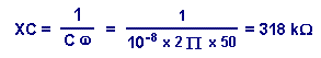
Indeed, by calculating the impedance of these at the working frequency (50 Hz), we see that it is :
By inserting resistors or capacitors, a part of the AC voltage is not rectified, but the percentage is practically negligible, given the high impedance of the circuit, compared to the much lower impedance of the use circuit.
The previous series assembly, allows to straighten higher voltages than one could have with a single rectifier.
When, in the same way, it is desired to obtain a current greater than that which can be provided by a single rectifier, it is possible to perform the parallel assembly.
This solution is possible, provided that the precautions specified for the series circuit are followed.
Indeed, rectifiers of the SAME TYPE and from the same manufacturer, are not identical and differ in the internal voltage drop (however low).
As a result, in the parallel arrangement, the rectifier having the lowest resistance, is traversed by a stronger current.
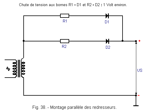
Here again, to restore equilibrium, a series resistor is inserted in each branch, so that the voltage drop across each branch is of the order of about one volt (Figure 38).
Thus, the differences in characteristics of one diode to another become negligible.
The value of the resistance depends here on the rectifiers used and more precisely on the current output.
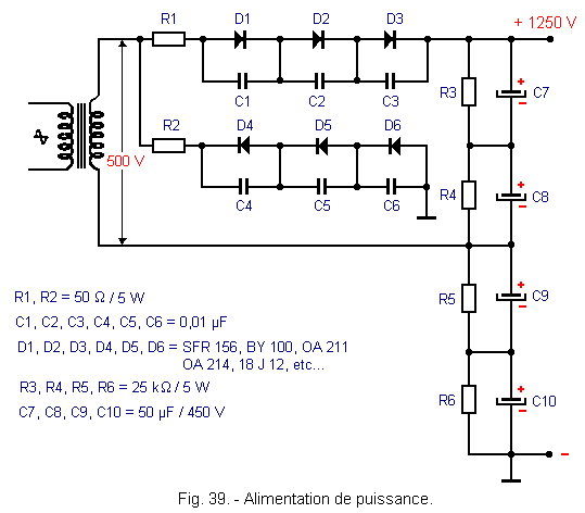
To obtain a large current and a high output voltage, it is possible with conventional type rectifiers to adopt the assembly of Figure 39.
A voltage doubler assembly with rectifiers in series is recognized.
Each diode is shunted by a capacitor of 10 000 pF and each capacitor of the doubler has a resistor in parallel, for the same reasons (distribution of the voltage).
However, as a general rule, it is most often used for power supplies (used mainly in industrial electronics) assemblies equipped with mercury vapor valves, thyratrons, ignitrons or thyristors).
Thus, this lesson ends with its particular and complementary montages and, to finish the notions of fundamental electronics, we will see Differential and Operational Amplifiers.


 Voltage Quadruple
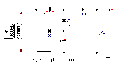
 Click here for the next lesson or in the summary provided for this purpose.
 Top of page
 Next Page