In previous theories, we have introduced almost all electrical quantities that are encountered in electronics with their respective units of measurement. We must now see how these magnitudes are measured, that is, how, in practice, we can know their value.
For this purpose, let us specify above all that, for the electronics engineer, it is essentially interesting to measure the current, the voltage and the resistance. Indeed, when we know the values taken by these three quantities at different points of the circuit, we can already have a precise idea of its operation and thus identify one of its possible failures.
In this lesson, we will see the most commonly used devices and circuits for measuring currents, voltages and resistances.
Let us first look at the current measurement because, as we shall see later, the measurements of the voltage and the resistance are made by means of this measurement.
In one of the previous theories, we told you that one could measure the electric current by exploiting one of the effects that it produces while crossing a conductor ; generally, we use the magnetic effect of the current, that is to say the property it has to produce a magnetic field around the conductors through which it passes.
In practice, the current to be measured passes through a coil and thus produces a magnetic field whose lines of force, shown in Figure 1-a, have the direction determined by the direction of flow of the current, according to the law of the pulls-plug.
We observe that these lines of force leave the right end of the coil and return by its left end after having crossed the outer space, in which they progress like the lines of force of a permanent magnet (figure 1-b) .
As far as the outer space is concerned, the coil behaves like a permanent magnet, and we can therefore consider as the north pole and the south pole the ends of the coil through which the lines of force come out and enter.
For these poles, we can also apply the general law we already know, according to which the poles of the same name repel each other, whereas the poles of opposite names attract each other; it can be seen, for example, thanks to the device of Figure 2, which, with particular modifications, also serves to measure the currents.
As seen in this figure, there is placed between the poles of a U-shaped magnet, a coil wound on a small light frame provided with two pivots which rely on special supports, so that the coil is free to rotate around a vertical axis.
Suppose that the winding is traversed by a current that flows in a direction such that it produces directed lines of force as seen in Figure 2-a ; the north pole and the south pole of the coil are in the positions indicated by this figure.
Under these conditions, we see that the north pole of the coil is pushed back by the north pole of the magnet and attracted by its south pole; in the same way, the south pole of the coil is repelled by the south pole of the magnet and attracted by its north pole, in agreement with the law of which we spoke above.
As a result of these repulsions and these attractions between the poles of the magnet and the coil, it turns in the direction indicated by the arrow of Figure 2-a, until it stops in the position of Figure 2-b, thus carrying its north pole near the south pole of the magnet and its south pole near the north pole of the magnet.
It has also been found that the repulsion and attraction forces exerted between the poles are all the greater as the current flowing through the coil is greater. This fact made it possible to use the device of Figure 2 for the measurement of the current.
For this purpose, the device is modified as in Figure 3-a and thus a current measuring instrument, also called a moving-frame galvanometer, is made because of the rotation that its coil can perform, which rotation serves to displace face of a graduated dial a needle attached to this coil.
Inside the coil is placed a small cylinder of soft iron which is fixed, that is to say which does not rotate with the coil, while the ends of the poles of the magnet are profiled so as to minimize the gap (or space occupied by air) in which the coil moves during its rotation.
The moving frame galvanometer can also be made differently although the principle remains the same. Instead of being horseshoe-shaped, the magnet may be cylindrical in shape and inserted within the voice coil as shown in Figure 3-b. In this case, a soft iron ring placed outside the coil closes the magnetic circuit.
With the adopted methods, we obtain for both types of galvanometers a large magnetic field and thus can be measured currents of very low intensity, because the forces due to this important field are sufficient to determine the rotation of the coil, even if the reduced current that runs through it creates a very weak field. In addition, the lines of force of the field produced by the magnet are arranged uniformly around the coil, which makes it possible to obtain a dial with equidistant graduations, as can be seen in Figure 3.
Note finally that around the pivots of the coil, there are two spiral springs, one end of which is fixed to the pivots and the other to the supports ; these springs are arranged so as to hinder the rotation of the coil and that is why they are called antagonistic springs.
To give an account of the function performed by the opposing springs, let us see the functioning of the instrument.
When no current flows through the coil, the springs hold it in such a position that its needle is opposite the left end of the dial, where the zero is inscribed ; this zero indicates that the current is zero. Under these conditions, it is said that the needle is in the rest position.
When a current flows through the coil, it rotates as we saw earlier and its needle moves to the right away from the rest position, as seen in Figure 3-a. The rotation of the coil then acts on the springs attached to the pivots by making them taut, which gives rise to forces that hinder this rotation, as they seek to push the coil and its needle to the left, that is to say say towards the rest position.
As the coil rotates, the springs tense more and more and therefore the forces which impede the rotation increase until they are equal to those which determine this rotation. Thus, the coil stops because there is a balance between the forces due to the current, which tend to turn it to the right, and the forces due to the springs, which tend to bring it to the left.
Suppose, for example, that the coil and its needle have stopped in the position shown in figure 3-a; if we now increase the current flowing through the coil, it starts to turn to the right because the forces that determine the rotation in this direction also increase at the same time as the current and the balance is broken. On the other hand, because of the new rotation, the springs are still stretched and the forces due to them increase in turn, until they again balance the forces due to the current ; when this occurs, the coil stops in a new position, farther than the previous one from the rest position.
We see in sum that at each value of the current corresponds a definite position taken by the needle. To measure the currents with this galvanometer, it is therefore sufficient to know the current values that correspond to the different positions of the needle. For this purpose, the coil of the galvanometer can be traversed by different currents of known value, firstly by a current of 1 mA, then 2 mA, then 3 mA, etc ... ; these values are then marked on the dial opposite the position taken by the needle for each current.
When these values are written on the dial, the galvanometer can be used to measure a current whose value is unknown : in fact, we can now read this value directly on the dial according to the position in which the needle stops when the galvanometer is traversed by the current to be measured.
For example, the numbers on the scale in Figure 3-b indicate the current value in milliamperes, as seen in the "mA" notation, the milliampere symbol, found under the dial.
If we therefore cross this galvanometer by a current of unknown value and if we see its needle stop opposite the number 1, as in Figure 3-a, we can say that the current has a value of 1 mA. Since this instrument is used to measure milliamps, it is called a milliammeter.
Of all the numbers written on the dial of a galvanometer, the most important is the one at the right end, that is to say at the end of the scale, because it indicates the caliber of the galvanometer, that is to say, the maximum current that he can measure.
The galvanometers of Figure 3 have a rating of 10 mA because, as we see in this Figure, the number inscribed at the end of the dial is precisely 10.
Each galvanometer is characterized by its caliber, which is a datum that must be remembered when using a specific galvanometer, to avoid having it pass through a current greater than the maximum current that it can measure. Indeed, if this happens, the galvanometer could deteriorate even more seriously as the current flowing through it is greater than its size.
Suppose, for example, that the galvanometer of Figure 3-a is erroneously traversed by a current of 20 mA. In this case, the forces which determine the rotation of the coil to the right are multiplied by two compared to those necessary to bring the needle to the end of scale. As a result, the needle very soon exceeds the end position and can be deformed by the violent impact against the stop which, as seen in Figure 3, is placed shortly after the end of the ladder, to stop the needle.
Another characteristic of a voice coil galvanometer is its internal resistance, that is to say the resistance that the current to be measured meets when it passes through this galvanometer ; this resistance is due to the wound conductor which constitutes the voice coil and may be between a few tens and a few hundred ohms, depending on the type of galvanometer.
In some cases, the internal resistance may have an influence on the measurement ; we can see this by examining the insertion of a current measuring instrument, that is, how to connect it to a circuit to measure the current flowing through it.
Since the current to be measured must cross the galvanometer, it is obvious that it must be connected in series with the circuit in which this current flows.
Suppose, for example, that we want to measure the current flowing in the circuit of Figure 4-a ; since this circuit is powered by a voltage of 20 V and has a resistance of 2 kΩ, the current flowing there is 20 / 2 = 10 mA.
We point out that, as resistance has been expressed in kilo-ohms, rather than in ohms, the current is expressed in milliamperes instead of being in amperes. Thus operations are simpler because they can be done with numbers that do not have too many zeros ; if, on the other hand, the ohm and the ampere had been used as units of measurement, we should have made the division 20 / 2000 = 0.01 Ampere = 10 mA.
Since the current has an intensity of 10 mA, we can measure it with a milliammeter of a 10 mA rating, like those of figure 3.
In Figure 4-b, we see the insertion of this galvanometer represented by a small circle inside which the inscription "mA" reminds that it is milliammeter.
Under the graphic symbol of the galvanometer, the 10 mA rating is indicated ; the internal resistance (r) of the milliammeter is also indicated, it is 500 Ω, that is to say 0.5 kΩ.
Since the milliammeter is connected in series, its internal resistance of 0.5 kΩ is added to that of 2 kΩ of resistance R and, after the insertion of the milliammeter, the circuit therefore has a total resistance of 0.5 + 2 = 2.5 kΩ.
Under these conditions, the current flowing through the circuit is 20 / 2.5 = 8 mA. We thus see that the insertion of the milliammeter disturbs the operation of the circuit, by passing from 10 mA to 8 mA.
The milliammeter will indicate a current of 8 mA, while in reality the current flowing through the circuit, when the instrument is not inserted, is 10 mA.
We can not therefore know exactly the intensity of the current, because the internal resistance of the galvanometer increases the resistance of the circuit and consequently decreases the current ; to obtain a more accurate measurement, we must use a galvanometer which has a much lower internal resistance.
For example, if a milliammeter is inserted into the circuit whose internal resistance is only 10 Ω, that is to say 0.01 kΩ, as in Figure 4-c, the resistance of the circuit will go from 2 kΩ to 2.01 kΩ and the current will be 20 / 2.019,95 mA.
This value differs only by 0.05 mA from the actual value of the current which is 10 mA, and in this case the measurement is sufficiently precise for the practical studies.
These examples allow us to conclude that a current measuring instrument provides all the more accurate indications that its internal resistance is lower.
Finally, it should be noted that, for the insertion of an instrument for measuring a current, it is necessary to take into account the direction of flow in which the current must flow through the voice coil.
We have seen that the direction of the lines of force, and therefore the poles which are created at the extremities of the coil, depend on the direction of circulation of the current ; if it circulated in the opposite direction to that in which it should circulate, the lines of force would also be directed in the opposite direction ; at one end of the coil, we would have the south pole instead of the north pole and vice versa.
As a result of this inversion of the poles, the direction in which the coil would turn would also be reversed and the needle would move to the left of the rest position, instead of the right. It would therefore leave the limits of the scale and it would not be possible to read the value of the current.
To prevent the galvanometer from being inserted in this manner, the manufacturer distinguishes the two ends of the coil by marking them with the signs + and -, to indicate that the current must travel through the coil from the positive end to the negative end, in agreement with the conventional sense that the current is directed from positive to negative.
These signs are also indicated next to the galvanometer in the diagrams of Figure 4 ; we can see that the current passing through the milliammeter is always directed from positive to negative.
The fact that the displacement of the needle depends on the direction in which the current flows in the voice coil has the consequence that an instrument of this type can not be used to measure the alternating currents. Indeed, these currents would travel the voice coil from its positive end to its negative end for half a period and in the opposite direction during the next half-period ; at each cycle of the current, the needle should first move to one side of the rest position and then to the other.
Take the example of the alternating current of the 50 Hz frequency sector. Since it performs 50 cycles per second, the needle should repeat 50 times per second this movement around the rest position. In reality, the needle can not perform such rapid movements and it remains in the rest position thus indicating a zero current.
Until now, we have examined a milliammeter with a rating of 10 mA but very often we must measure currents of greater intensity, reaching a few hundred milliamperes. These currents can be measured with the same galvanometer as the one we have just seen, by increasing its size.
For this purpose, let us refer to the circuit of Figure 5-a, where the battery of 100 V circulates in the resistance of 5 kΩ a current of 100 / 5 = 20 mA and suppose that one wants to measure this current with a galvanometer which has a size of 10 mA.
Since the gauge of the galvanometer (10 mA) is equal to half of the current to be measured (20 mA), it is necessary that there is only half of the current which passes through the galvanometer so as not to overload it.
The galvanometer is therefore connected in parallel with a resistor, called a shunt resistor or, more simply, a shunt, so that the other half of the current, which must not traverse the instrument, can pass through it.
For this, the shunt must have a resistance equal to the internal resistance of the instrument; since in the case of Figure 5-a, the milliammeter has an internal resistance (r) of 10 Ω, the value of 10 Ω has therefore been adopted for the resistor Rs of the shunt. Thus, the current (I) of 20 mA arrived at point A, divides into two equal currents of 10 mA each ; one travels the shunt, while the other crosses the galvanometer, which indicates the value of 10 mA.
The galvanometer which has a shunt connected to its ends thus measures half of the current flowing in the circuit; we can therefore know its value by multiplying by two the value read on the dial.
In this particular case, the shunt serves to multiply the milliammeter gauge by two and makes it possible to know the value of the currents up to a maximum of 20 mA ; but one can also triple, quadruple, etc., the caliber of a galvanometer, by correctly choosing the value of the shunt.
For example, in Figure 5-b, we can see how the gauge of the galvanometer discussed above can be increased fivefold to measure currents up to a maximum of 50 mA.
In this case, in order for a maximum current of 10 mA to still pass in the galvanometer, the shunt must be traversed by a current of 40 mA, four times more intense. This is obtained by giving the shunt a value four times smaller than that of the internal resistance of the galvanometer, that is to say a value of 2.5 Ω (10 / 4 = 2.5 Ω). Thus, the galvanometer measures only one fifth of the current flowing in the circuit and its value is obtained by multiplying by five the value read on the dial.
In a general way, let Ig be the maximum current of the galvanometer and Ic the maximum current that we want to measure, and therefore the caliber. The resistance Rs of the shunt is traversed by the current Ic - Ig : one has the relation Rs (Ic - Ig) = r x Ig is :
Rs = Ig / (Ic - Ig) x r
This formula therefore makes it possible to calculate the resistance of the shunt from the internal resistance r of the galvanometer, its maximum current Ig and the desired size Ic.
The possibility of easily increasing the size of a galvanometer thanks to the shunts makes it possible to use not only milliammeters but also microamperes, that is to say instruments whose size is of the order of microamperes. The use of instruments with a very low end-of-scale current is useful in electronics for measuring voltages, as we will see.
The electrical voltage can be measured with the same voice coil galvanometer that was used for current measurement.
To see this, see figure 6-a on which the circuit of figure 4-c, was again postponed, with the only difference that the resistance R, instead of having the value of 2 kΩ, that is to say, 2 000 Ω, to the value of 1 990 Ω. In this way, taking into account the internal resistance of the milliammeter, which is 10Ω, the circuit has a total resistance of : 1 990 + 10 = 2000Ω, or 2 kΩ ; it circulates a current of 10 mA which is exactly that indicated by the galvanometer.,
Note now that the galvanometer indicates the current of 10 mA when the battery applies a voltage of 20 V to the instrument and the resistor in series, that is to say to the two elements between the points indicated by A and B in Figure 6-a. Indeed, according to the law of OHM, the voltage of 20 V of the battery must be equal to the product of the current of 10 mA which traverses the instrument by the "resistance" placed in series (the resistance of 2 kΩ presented in total by these two elements). We have then : 10 x 2 = 20 V.
We understand why, even if we did not know the value of the voltage of the battery, we could always determine it by multiplying the current indicated by the galvanometer by the resistance of 2 kΩ.
Suppose for example that the battery of 20 V is replaced by another battery having an unknown voltage and that, under these conditions, the milliammeter indicates a current of 6 mA ; by multiplying this current by the resistance of 2 kΩ (6 x 2 = 12 V), we find that the new battery provides a voltage of 12 V.
The assembly formed by the galvanometer and the resistor placed in series can therefore be used to measure the voltage applied between the ends A and B of these two elements.
As we have seen, to know the value of this voltage, multiply the current indicated by the galvanometer by the resistance between points A and B ; however, this multiplication can be avoided by writing the voltage values directly to the instrument, as shown in Figure 6-b.
Above the scale of the instrument which, as we have seen in Figure 3, is used to read milliamps, a second scale has been made. Each value of the voltage is written in front of the value of the current indicated by the galvanometer when it is applied between the points A and B.
For example, the value of 20 V is written opposite the value of 10 mA because the galvanometer indicates this current when this voltage is applied between A and B.
Since the galvanometer directly indicates voltage in volts, the milliammeter with the series resistor is called the voltmeter.
In the diagrams, the voltmeter is generally not represented by the milliammeter symbol with a series resistor, but by the one indicated in Figure 6-c, that is to say by a small circle in which is inscribed the Lette V, symbol of volt. Next to the graphical symbol of the voltmeter, the caliber and the internal resistance are indicated.
The voltmeter rating indicates the maximum voltage that can be measured : the voltmeter of Figure 6 has a rating of 20 V because with this voltage, the milliammeter needle is at the end of the scale.
With regard to the internal resistance, the total resistance obtained is given for the voltmeter by summing the internal resistance of the milliammeter and the resistor placed in series : the voltmeter of Figure 6 therefore has an internal resistance of 2 kΩ.
The resistance that is connected in series to the milliammeter for use as a voltmeter is called additional resistance. Its value determines the gauge of the voltmeter.
Suppose, for example, that we want to use the milliampemeter examined so far to achieve a 50 V voltmeter.
This means that an end-of-scale current of 10 mA must pass through the milliammeter when a voltage of 50 V is measured ; according to the law of OHM, the voltmeter must have an internal resistance of 50 / 10 = 5 kΩ, that is to say 5000 Ω.
Since the milliammeter has an internal resistance of 10 Ω, an additional resistance of 5000 - 10 = 4990 Ω must be used.
Let us remember then that the value to be given to the additional resistance is obtained by dividing the maximum voltage which one wants to measure by the end-of-scale current of the galvanometer and by subtracting from the result obtained the internal resistance of the instrument.
Note finally that in Figure 6-c the voltmeter's ends are indicated by the signs + and - because the current passing through the voltmeter thanks to the voltage that is measured must be directed from positive to negative so that the needle moves to the right.
Obviously, with this type of voltmeter, we can not measure AC voltages because they would circulate the current not only from positive to negative but also from negative to positive.
Since in electronics, it is also interesting to measure alternating voltages, they are converted into DC voltages using diodes.
A voltmeter can be used to measure the voltage not only at the ends of a cell but also between two points of a circuit between which there is a potential difference.
For example, the voltage of 20 V which exists at the ends of the 2 kΩ resistor connected between the points A and B in the circuit of Figure 7-a, can also be measured with the voltmeter of Figure a 20 V caliber
As seen in Figure 7-b, the voltmeter is connected in parallel to the resistance, that is to say between the points A and B between which is the voltage to be measured.
The difference between this type of insertion and that used to measure the current is obvious : to measure the current passing through the resistance, the milliammeter must be connected in series, while to measure the voltage between the ends of the same resistor, the voltmeter must be connected in parallel.
When the voltmeter whose internal resistance is also 2 kΩ is connected in parallel with the 2 kΩ resistance, the conductance between the points A and B of Figure 7-b is doubled. The resistance between these two points is reduced by half, that is to say 1 kΩ. By adding this resistance to that of 4 kΩ of the resistance connected between the points B and C, we see that after the insertion of the voltmeter, the circuit presents in total a resistance of 5 kΩ.
Under these conditions, a current of 60 / 5 = 12 mA runs through the circuit whereas before the insertion of the voltmeter the current was 10 mA, as seen in Figure 7-a ; this means that the insertion of the voltmeter disturbs the operation of the circuit by varying the current flowing there, because part of this current must pass through the voltmeter.
Since the voltmeter has an internal resistance equal to that of the resistor to which it is connected, the current of 12 mA is divided into two currents equal to 6 mA each, one of which traverses the resistance and the other the voltmeter.
At the ends of the 2 kΩ resistor in which the 6 mA current flows, a voltage of 6 x 2 = 12 V is obtained, which is indicated by the voltmeter. This is confirmed by Figure 6-b which shows that the instrument indicates a voltage of 12 V when crossed by a current of 6 mA as happens precisely in this case.
The voltmeter therefore indicates a voltage of 12 V, 8 V lower than that between A and B when the voltmeter is not inserted into the circuit
(figure 7-a).
As we said, this error in the measurement is due to the current that must pass through the voltmeter, because if the instrument did not absorb current, it would not vary the one that circulates in the circuit before insertion.
To limit the error in the measurement, it is necessary to reduce the current flowing through the voltmeter ; this can be achieved by employing a milliammeter with a low intensity end-of-scale current. That's why in electronics we use milliammeters and microamperes, as we have already pointed out.
The voltmeter of Figure 7-b greatly disrupts the operation of the circuit because it consists of a milliammeter of an end-of-scale current of 10 mA, equal to that flowing in the circuit before insertion.
If, on the other hand, a voltmeter consisting of a milliammeter with an end-of-scale current of 1 mA was used, that is to say equal to one tenth of that which normally circulated in the circuit, its insertion would disturb it much less. the operation and make the measurement more accurate.
To switch the current of 1 mA in this instrument when measuring a voltage of 20 V, it is necessary that the voltmeter has an internal resistance of 20 / 1 = 20 kΩ, ten times higher than that of the voltmeter of Figure 7-b.
A voltmeter therefore disturbs the circuit to which it is connected, and thus furnishes measures all the more just in proportion as its internal resistance is greater; but this resistance also depends on the size of the voltmeter, as we have seen previously.
To be able to compare two voltmeters independently of their size, we indicate the internal resistance they present for each volt.
This data, which indicates the sensitivity of the voltmeters, can be easily determined by dividing the internal resistance by the caliber : the sensitivity of a voltmeter is expressed in ohms per volt (W / V).
The voltmeter of Figure 7-b having an internal resistance of 2 kΩ, that is to say 2 000 Ω is a 20 V gauge, has a sensitivity of :
2 000 / 20 = 100 W/ V
On the contrary, the voltmeter having an internal resistance of 20 kΩ, that is to say 20 000 Ω and a caliber of 20 V, has a sensitivity of 20 000 / 20 = 1 000 Ω / V. It is thus ten times superior to the previous one.
We can therefore conclude that a voltmeter provides indications all the more just as its sensitivity is greater.
Since it is important to introduce the least possible disturbance into the circuits in order not to distort the measurements, voltmeters with a sensitivity of less than 1 000 Ω / V in electronics are not used and very often voltmeters with a sensitivity of 5 000 Ω / V to 10 000 Ω / V and even 20 000 Ω / V, for which microamperes are used.
A voice coil galvanometer can also be used to measure electrical resistance by means of a circuit of the type shown in Figure 8-a. As we shall see, the galvanometer indicates on a special dial the value of the resistances which are connected to the ends A and B of the circuit.
The elements of this circuit are chosen so that the needle of the instrument is at the end of the scale when one connects, a simple conductor of very weak resistance (Figure 8-b) between the ends A and B, that is to say is, when these ends are short-circuited.
Using a 4.5 V battery and 1 mA galvanometer to circulate this current and determine the needle displacement at the end of the scale, the circuit resistance given by the voltage of the cell divided by the current, ie 4.5 kΩ (4.5 / 1 = 4.5). Since it is assumed that the instrument has an internal resistance of 0.1 kΩ, a resistance of 4.4 kΩ has been connected in series.
If we want this galvanometer to indicate the resistance that exists between points A and B, then we have to write the number zero at the end of the scale, as we see on the right side of Figure 8-b, since the needle is precisely in this position when these points are short-circuited and so there is between them a resistance equal to zero ohm.
If on the contrary, between points A and B a resistance of 4.5 kΩ is inserted, as in figure 8-c, the resistance of the circuit is doubled and consequently the current is halved; the needle thus arrives at the half of the dial, that is to say in the middle of the scale, as indicated in the right part of figure 8-c.
So we have to enter the number 4 500 at this position, it indicates the value in ohms of the "resistance" connected between points A and B.
If no resistance is connected between A and B, as in Figure 8-a, the instrument needle remains in its rest position (shown in the left-hand part of Figure 8-a) because no current circulates in the circuit. We may therefore remember that, under these conditions, there is between A and B an infinitely great resistance ; this is why we put the sign 8 opposite the rest position of the needle ; this sign indicates an infinitely large value.
If we insert between A and B other resistances of known value, we can mark this value on the dial in front of the scale on which the needle stops ; thus, one can read directly on the dial the value of the resistances connected between A and B.
Thus, an ohmmeter has been produced, that is to say a device that makes it possible to measure the value of the resistances in ohms.
It can be seen in Figure 8 that the dial of the ohmmeter has its zero at the right end, unlike the milliammeter and voltmeter dials which have their zero at the left end, as can be inseen in Figure 6-b.
The type of ohmmeter thus described has a disadvantage. Indeed, as it is used, the battery wears and provides a voltage of less than 4.5 V ; consequently, the current flowing in the circuit decreases and the needle no longer reaches the end of the scale when, between A and B, there is a resistance of zero value.
Under these conditions, the needle no longer indicates the marked zero value at the end of the scale, although the measured resistance has a value equal to zero. There is a similar error on all other points of the dial.
To eliminate these measurement errors, it must be ensured that the needle can reach the end of the scale even when the battery voltage decreases ; this is why the circuit is modified (Figure 9).
The value of the resistance connected in series to the instrument has been reduced to 3.9 kΩ so that the total resistance of the circuit is 4 kΩ and that the current of 1 mA can circulate there, even when the voltage the battery goes down to 4 V (4 / 4 = 1).
But when the battery is new, a current greater than 1 mA flows in the galvanometer and the needle then moves farther than the end of the scale. It is remedied by connecting in parallel on the galvanometer an adjustable resistance, as seen in Figure 9. Thus, only a portion of the current passes through the device.
Since the resistance is adjustable, its value can be adjusted so that the current in the instrument keeps the value of 1 mA when the battery voltage decreases from 4.5 to 4 V.
Before using the ohmmeter, it must therefore be zeroed, which consists in shorting the ends A and B and adjusting the adjustable resistance so as to bring the needle of the instrument to the zero of the dial of the ohmmeter. Therefore, we can remove the contact between A and B and put between these points the resistance of which we want to measure the value ; this will be accurately indicated by this instrument.
Finally we observe that since the resistance of the circuit has been reduced to 4 kΩ, the needle is in the middle of the scale when the value of the resistance placed between A and B is 4 kΩ, as can be seen in the Figure 9, and no longer 4.5 kΩas shown in Figure 8-c.
In this case, the number 4 000 should be entered in the middle of the scale (as in figure 9) because this number indicates in ohms the value of the resistance placed between A and B.
So remember that the resistance marked in the middle of the scale of an ohmmeter also indicates the resistance of the circuit of the ohmmeter itself.
Thus, we have seen that measurements of current, voltage and resistance can be made using a single voice coil galvanometer inserted in a suitable circuit.
For electronic measurements, universal controllers are used which include, in addition to the galvanometer, additional shunts and resistors to increase the gauge in the current and voltage measurements, as well as the battery and the adjustable resistance required for the ohmmeter.
These elements can be connected to the galvanometer to achieve a circuit adapted to the type of measurement that must be done ; in this case, the galvanometer is equipped with several scales that measure currents, voltages or resistances in a wide range of values.
To finish this lesson, we show you a diagram of the universal controller and that will allow you to understand in order to know how to read on it and now, you must know all the components of the latter including its operation already explained above.
Compared to the known partial drawings, that of Figure 10 shows the presence of the fuse of 1 A placed in series with the socket "common". This fuse protects the entire controller.
It also appears the capacitor 0.1 µF - C10, placed in series with the socket "BF", whose role is to eliminate any DC component possibly superimposed on the controlled low frequency signal. The BF socket makes it possible to measure the decibel, that is to say the loudness coming for example from the loudspeakers.
The electrical characteristics of the galvanometer are not unknown to you, its end-of-scale current is 40 µA and its internal resistance of 1 200 Ω.
The galvanometer must not be crossed by a current greater than 40 µA.
If following a connection error the galvanometer was traversed by a current much higher than 40 µA, it would result in serious damage. It is therefore necessary to protect the galvanometer against overcurrent by means of two silicon diodes. As shown in Figures 10 and 11, the diodes are connected head to tail across the galvanometer.
To understand how these components fulfill their role, it must be remembered that the full conduction of a silicon diode requires a potential difference between the anode and its cathode of at least 0.6 to 0.7 V. This voltage constitutes the conduction threshold of the diode ; below this value, the diode is blocked and the current flowing through it can be considered negligible.
Thus, by connecting two silicon diodes to the galvanometer according to the principle of Figure 11, it is avoided that the voltage across the galvanometer (between points A and B) exceeds 0.6 V.
If between A and B manifests a voltage greater than 0.6 V and if the current (I) flows from A to B (Figure 11-a), the diode D4 goes into conduction ; if on the other hand, the current flows from B to A (Figure 11-b) the diode D3 leads.
In either case, the conducting diode behaves like a shunt resistor of low value and limits the maximum value of the current flowing in the voice coil, thus avoiding a certain deterioration.
For intensity values ??less than or equal to that of the end of scale of the galvanometer (40 µA), the voltage at the terminals of the latter is well below the threshold of conduction of the diodes and their presence has no influence on the operation of the galvanometer or the result of the measurement (Figure 11-c).
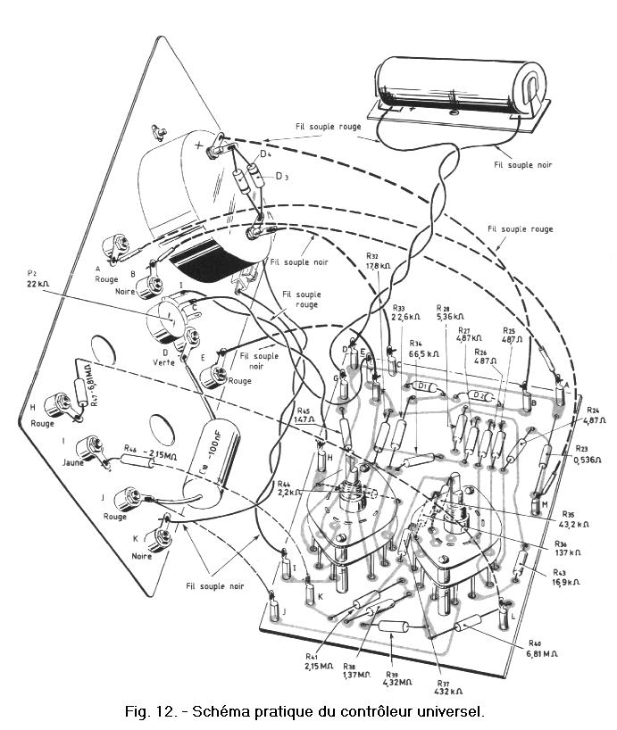
We refer you to the practical diagram of the universal controller (figure 12) so that you can realize at the level of the practice. The latter varies between 50.00 to 150.00 euros depending on the accuracy of the components and its sensitivity. In addition, there are devices with digital display, more accurate than the galvanometer but more expensive.
This diagram below shows all the assembled components and the different connections made between them. On the latter also appears the battery of the ohmmeter.
With the aid of the practical diagram, it is possible to perform a final verification of the assembly.
In the next we will continue the lessons of semiconductors (See the Basic Electronic Summary) to complete our knowledge of electronics, concerning all semiconductors, NPN or PNP transistors, integrated circuits, diodes, etc. ...


 Current measurement
 Click here for the next lesson or in the summary provided for this purpose.
 Top of page
 Next Page