We have seen in the preceding lesson how graphically we represent an alternating current, and what are the magnitudes which characterize it ; we will now examine the alternating voltage.
1. - ALTERNATIVE VOLTAGE :
To determine the form of the AC voltage, we must remember that it is bound by the OHM law to the current flowing through the resistance ; as we already know the form of the alternating current, it is easy for us to look for the shape of the tension which determines the passage of this current in the resistance.
Let us see, for example, how one can graphically represent the alternating voltage that circulates the alternating current in a circuit comprising a resistance of 5 ohms (Figure 1-a).
We observe first that at the beginning of the period (0 s), at half (0,1 s) and at the end of the period (0,2 s), the current is zero : if at these moments, the current does not flow in the circuit, it means that the voltage supplied by the generator is also zero.
When, on the other hand, the current reaches the maximum value (Imax) after 0.05 s, and (- Imax) after 0.15 s, the voltage also reaches at these times the corresponding maximum value Vmax and -Vmax (certain We will note Imax by IM and Vmax by VM).
Since the maximum value of the current is three amperes, it is necessary to pass this current in a resistance of five ohms, a voltage which, according to the law of OHM, is given by the product of the value of the resistance by that of the current : the maximum value of the voltage is therefore 5 x 3 = 15 V.
In the same way, we can obtain the value of the tension at any other moment, by multiplying the value of the resistance by that of the current taken at this moment.
The values thus obtained are shown in the diagram of Figure 1-b. On the horizontal axis of this diagram, the times are indicated in the same way as for the current, that is to say that each centimeter corresponds to 0.025 s. On the vertical axis of the diagram, the voltages (U) expressed in volts (V) are now indicated ; 1 cm corresponds to 5 V, as indicated by the inscription "1 cm = 5 V" reported above and to the right.
Since the value Imax of the current is reached after 0.05 s, the value Vmax of the voltage corresponds to this same moment ; we proceed in the same way for the value -Imax, but since this value is below the horizontal axis, the corresponding value of the voltage -Vmax is also under this axis.
If the other values of the voltage are reported in the same way, for example those taken after 0,025 s, 0,075 s, 0,125 s and 0,175 s, one obtains a certain number of points which make it possible to draw the line of the figure 1-b by joining them ; this curve indicates the pace of the AC voltage. As expected, it is also a sinusoid, so we can say that the alternating voltage, too, has a sinusoidal shape.
(For your convenience, we report the same diagram below).
As we have already done for the current, we can therefore consider the alternating voltage as a succession of cycles, all identical, in each of which the same values are always repeated.
The time that the voltage takes to complete a cycle is called the period of the alternating voltage and it also divides into two equal half-periods, one positive and the other negative ; in the first, the values of the voltage are indicated by positive numbers, while in the second, the same values are indicated by negative numbers.
This fact tells us that the generator reverses its polarities at each half-period ; in Figure 1-b, the values of the voltages supplied by the generator are indicated by positive numbers when the latter has its polarities as in Figure 1-c, while the values of the voltages are indicated by negative numbers when the generator reverses its polarities as in Figure 1-d.
Note that, after designating the poles of the generator by A and B, it was considered that the positive current was that coming from the pole A of the generator, as in Figure 1-c, and that the negative current was on the contrary that which entered the generator through the pole A, as in Figure 1-d. It was also considered that the voltage was positive or negative when the pole of the generator designated by A was positive, as in Figure 1-c, or negative, as in Figure 1-d.
This process must be remembered because it will still be used in this lesson.
We now observe that the AC voltage must obviously have the same period as the current, as we immediately verify by comparing Figures 1-b and 1-a : the current and the voltage complete the same cycle in one second and they have the same frequency.
To characterize an alternating voltage, we must therefore indicate, not only its period or its frequency, but also its value : as for the current, we indicate the value obtained by dividing by 1.41 the maximum value of the Alternative Voltage (valid only for sinusoidal mode).
When we say, for example, that the available grid voltage in our homes has a value of 110 V or 220 V, we refer to the rms value of this voltage ; the voltage indicated on electrical appliances that operate on alternating current is the value of the voltage with which these devices must be powered.
The value of a sinusoidal AC voltage across a resistor R is the value of a DC voltage whose current would produce the same heating effects as the sinusoidal alternating current in the same resistor R and during the same time. In this way, an equivalence is established between the AC voltage and the DC voltage, with regard to the heat effects produced by the currents which they circulate.
In practice, this means, for example, that a soldering iron provided for a voltage of 220 V can be powered by either an alternating voltage that has an effective value of 220 V or a DC voltage of 220 V. In both cases, the soldering iron produces the same amount of heat because the alternating voltage circulates in its resistance a current whose rms value is equal to that of the DC voltage.
The direct current flowing in the soldering iron can be obtained, according to the OHM law, by dividing the DC voltage by the resistance of the soldering iron ; in the same way, if we divide the rms value of the AC voltage applied to the soldering iron by its resistance, we can obtain the rms value of the current which feeds it.
So we see that with the rms values, we can perform the calculations for the alternating current as if it were a direct current, not only with regard to the heat produced by the current, but also for the use of OHM law.
But it must be remembered that the equivalence between AC and DC is valid only with respect to the thermal effect : this means that we can not consider AC as a DC current only in circuits formed exclusively of resistive elements that transform electrical energy into heat.
In previous lessons, we have seen other elements, such as capacitors and coils, that do not dissipate electrical energy but store it by creating an electric or magnetic field, respectively.
For capacitors and coils, the equivalence between alternating current and direct current is no longer valid, since these elements do not give rise to the production of heat. However, in the case of circuits which include capacitors or coils, the rms value of the voltage and current is also indicated, but always with reference to the thermal effect.
When we say, for example, that a coil is traversed by an alternating current of an effective value of 2 A, we indicate an alternating current which would produce, if it crossed a resistance, the same quantity of heat as that produced by a direct current of 2 A.
We must therefore remember that, for the alternating and sinusoidal quantities, the rms value is always given, even in the case of circuits in which no thermal effect occurs.
As we have seen above, the resistance offered by the resistive element to the alternating current is obtained by dividing the rms value of the voltage by that of the current, as well as in continuous mode. This means that the "resistances" have the same behavior in the continuous mode as in the alternating mode, because they offer the passage of the two currents a resistance which is equal for the two regimes to the ratio of the voltage by the current.
On the contrary, capacitors and inductances will need to be examined separately according to the regime applied.
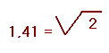
The representation used so far, of drawing the sinusoid which indicates the values of the voltage or current during a complete cycle, is not very convenient ; we have therefore adopted another system of representation which has the advantage of highlighting many properties of the alternative quantities which do not appear clearly on the design of the sinusoid.
The sinusoid representing an alternating quantity is drawn as illustrated in Figure 2, by rotating a segment of length equal to the maximum of the sinusoid and reporting point by point the ordinates of its end.
So to represent a voltage or an alternating current, it is enough to postpone in an orthogonal coordinate system projections perpendicular to the ordinate axis of the vector rotating at the chosen instants.
This plotting method is called the vector representation where the sinusoidal alternatives are obtained thanks to a vector characterized by :
- a length proportional to the maximum amplitude (or elongation) of the alternating and sinusoidal quantity ; if, for example, we want to represent a sinusoidal voltage of value Vmax = 300 V, we can choose to take a scale with 1 cm for 100 V and draw a vector of length 3 cm corresponding to 300 V.
- a constant counterclockwise speed of which a complete turn represents the period of the sinusoidal magnitude. Thus the vector accomplishes in a second a number of turns equal to the frequency of the quantity considered.
- a position for which its ordinate represents the value of the quantity considered at this precise instant.
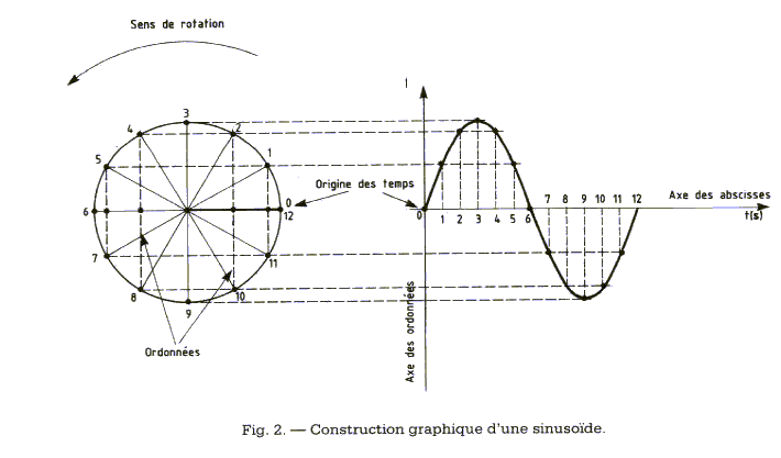
To better understand this method, we give six examples are reported Figure 3.
Figure 3-a represents a sinusoidal alternating current of maximum value Imax = 0.5 A corresponding to 1 cm on the ordinate axis. The representative vector 1 cm long is the origin of times (0s) in horizontal position, meaning that its ordinate is zero, as is the value of the sinusoid. This vector having performed a complete revolution, the value of its ordinate taken at precise times and reported in the orthogonal coordinate system, will describe the sinusoidal shape of the current of Figure 3-a.
Figure 3-b represents a sinusoidal alternating voltage of maximum value Vmax = 20 V corresponding to 2 cm on the ordinate axis. The representative vector 2 cm long in advance of 90° with respect to the origin of the times (0s) is in a vertical position, meaning that its ordinate is maximal and positive, just as is the value of the sinusoid. This vector having performed a complete revolution, the values of its ordinate taken at precise times and reported in the orthogonal coordinate system will describe the sinusoidal shape of the current of Figure 3-b.
Figure 3-c represents a sinusoidal alternating current of maximum value Imax = 1.5 A where 1 cm corresponds here to (1 A) on the ordinate axis. The representative vector 1.5 cm long placed at 180° from the origin of the times (0s) is in the horizontal position, oriented to the left (contrary to that of Figure 3-a), meaning that the value of the sinusoid is zero. Only this time, the sine wave will start with negative values when the vector completes its counter clockwise turn ; the plot remains the same as the previous ones (figures 3-a and 3-b).
Figure 3-d represents a sinusoidal alternating voltage of maximum value Vmax = 50 V where 1cm corresponds here to 100 V on the ordinate axis. The representative vector of 0.5 cm long positioned at 270° from the origin of the times (0s) is in the vertical position, facing downwards (contrary to that of Figure 3-b) because the sinusoid begins with an extremum (maximum value) negative.
We see in the examples given that the vector is positioned where the sinusoid begins to indicate its value at this precise instant (t = 0s). It should be known that the angle formed by the vector and the horizontal axis is reached according to a time (t) which will be reported on the abscissa (horizontal axis), see figure 2.
In the example of Figure 3-e, the current vector Imax = 0.5 A of Figure 3-a is represented with a 30° advance with respect to the origin of the times. In Figure 3-f, the vector of the current Imax = 1.5 A is represented with an advance of 330° with respect to the origin of the times.
In general, it is more interesting, at a given moment, to compare the position of the vectors than to know their value.
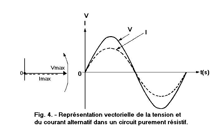
Figure 4 illustrates the vectors representative of the voltage and the current in a purely resistive circuit like that of Figure 1. Since the two sinusoids start at the origin of the times, the two vectors are horizontal and superimposed.
The two vectors, rotating around the point 0 at the same speed, generate two sinusoids (V, I) of the same speed, obtained by the ordinate of the two rotating vectors.
When the values of two quantities simultaneously reach the extremums (maximum and minimum) and join on the x-axis to cancel each other out, we say that these two sinusoids are in phase.
So when two alternating quantities of the same frequency are in phase, the representative vectors are superimposed and rotate at the same speed.
At each turn the vector describes an angle of 360° ; if it completes one revolution in one second, its rotational speed will be 360° per second (360° / s), for "n" turns per second will be n x 360° per second.
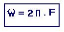
Generally, angles are expressed in radians : angles that intercept an arc of a length equal to radius. Since 360° corresponds to 2 n radians, we can express the speed of rotation by 2n x n radians per second.
A cycle of an alternative magnitude corresponds to a complete revolution of the representative vector and the number of turns "n" performed in one second represents the number of cycles per second of the sinusoid, also called frequency (F).
The velocity of the representative vector will be called the pulsation (symbol
(omega-unit of measurement symbol in rad / s) and expressed by the relation :


 Vector representation of alternative quantities
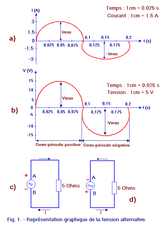
 Click here for the next lesson or in the summary provided for this purpose.
 Top of page
 Next Page