After having seen the functioning of the electronic tube triodes exposed in the previous lessons, we will study an extremely important category of circuits in electronics : Multivibrators.
Multivibrators are square wave generators.
They are divided into three categories : astable, monostable, bistable multivibrators.
The former produce a square waveform with no control signal.
The second ones deliver a square pulse, after the application of a control pulse.
The latter produce a sudden change in voltage, each time they are controlled by an impulsive input signal.
Before beginning the study of these circuits, it is necessary to give some precisions concerning the square or rectangular waves.
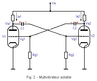
It is a square wave generator formed by a two-stage amplifier with RC links, but whose output is connected directly to the input.
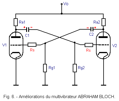
Figure 2 shows the diagram of an astable multivibrator, often called the ABRAHAM BLOCH multivibrator, equipped with two triodes.
STARTING THE ASSEMBLY :
As soon as the high voltage is applied, the two tubes V1 and V2 begin to drive.
Although the mounting is symmetrical, currents Ia1 and Ia2 are not equal.
Indeed, it is necessary to take into account the tolerances of the elements which make that their values are not rigorously identical.
Suppose that Ia1 increases faster than Ia2, so Va1 decreases faster than Va2.
The capacitor C1 instantly transmits the voltage variation DVa1 across the resistor Rg2 and C2 transmits the voltage variation DVa2 across Rg1.
These voltage variations are negative and we can say that Vg2 is more negative than the voltage Vg1.
As a result, the tube V1 leads much more than the tube V2.
The phenomenon amplifies rapidly (cumulative effect) and V2 is blocked, while V1 leads to saturation.
At the same time, as soon as the circuit is energized, the capacitor C1 quickly charges through Ra1 and through the resistance equivalent to Rg2 and to the internal grid-cathode resistance of the tube V2.
Similarly, the capacitor C2 charges through Ra2 and through the resistance equivalent to Rg1 and internal resistance gate-cathode tube V1.
The charges of C1 and C2 are very fast because they are carried out through resistors of low values (anode resistors and gate-cathode resistors of each tube).
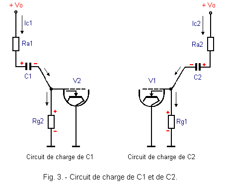
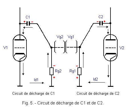
Figure 3 shows the charging circuits of the capacitors C1 and C2, as well as the polarities of the voltages appearing across Rg1 and Rg2.
DETAILED OPERATION OF THE ASSEMBLY
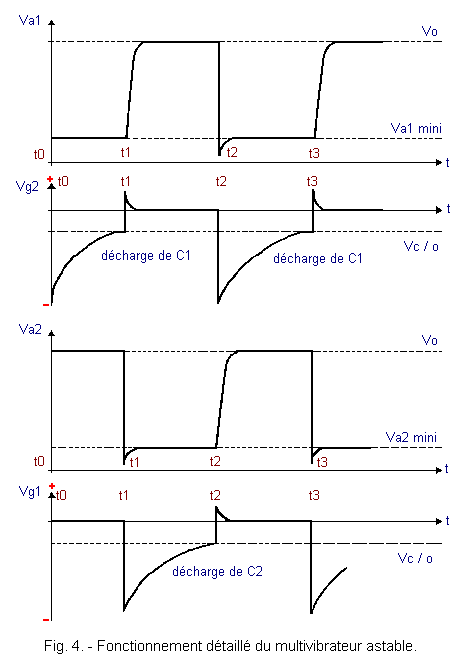
To explain the operation of the multivibrator, we will use Figure 4 where are represented the voltages Va1, Va2, Vg1, Vg2, and decompose a period in time intervals corresponding to different phases of operation.
Consider editing at time t0, that is just after the start period.
-V1 strongly drives and Va1 is equal to Vo - Ra1 x Ia1 that is to say a value lower than Vo (Va1 mini).
-V2 is blocked, so Va2 is equal to Vo.
-Vg1 is very close to the potential of mass, since Rg1 does not receive any variation coming from the anode of V2.
-Vg2 is strongly negative (well below the blocking voltage).
- Capacitors C1 and C2 are charged to a value close to the high voltage.
Between t0 and t1 :
The capacitor C1 charged to the high voltage sees the tension of its positive armature decrease sharply, as soon as the tube V1 begins to drive.
It can then be discharged through the internal resistance of V1 and the resistance Rg2.
This discharge is slow because the gate resistance Rg2 has a high value.
The discharge current Id1 causes a voltage drop across Rg2, according to the polarities indicated in Figure 5.
This negative voltage on the gate of V2 keeps the tube blocked, but it decreases as the load is extended.
The voltages Va1 and Va2 respectively keep their value Va1 mini and Vo.
At the instant t1 :
The gate voltage Vg2, which rises slowly towards the ground potential, reaches the cut-off voltage of the tube V2.
The tube V2 starts to drive and therefore the voltage Va2 goes from the value Vo to the value Va2 mini.
This sudden negative variation of the anode voltage of V2 is transmitted instantaneously to the gate of V1 by the capacitor C2.
The tube V1 is blocked and the anode voltage Va1 rises from Va1 mini to Vo.
In reality, the voltage change on the anode of V1 is in an exponential form.
Indeed, as soon as the voltage Va1 increases, the capacitor C1 is charged through the circuit described in Figure 3.
The charging current Id1 brakes the rising of the anode voltage and causes the appearance of the small positive peak across the resistor Rg2.
At the instant t1 to t2 :
The tube V1 is blocked and the tube V2 leads.
The capacitor C2 can be discharged through the tube V2 and the gate resistor Rg1 of the tube V1 (see Figure 5).
The discharge current Id2 determines a negative voltage on the gate of V1 and maintains the latter blocked.
This negative voltage (Vg1) rises slowly towards the ground potential until time t2.
Between instants t1 and t2, we find that Va1 remains equal to Vo and Va2 to Va2 mini.
At the moment t2 :
the capacitor C2 is almost discharged and the negative gate voltage Vg1 reaches the cut-off voltage of the tube V1.
The latter begins to drive and sees its anode voltage Va1 decrease sharply.
The negative variation is transmitted instantaneously to Rg2 by the capacitor C1.
The tube V2 is blocked and the anode voltage Va2 goes from the value Va2 min to the value Vo.
This rise is exponentially because during this time, the capacitor C2 is charging again to the high voltage through its circuit shown in Figure 3.
Just as at time t1, the charge of capacitor C2 causes the rounding of voltage Va2 and the small positive peak of voltage Vg1.
This positive voltage of the gate voltage of the tube V1 has an effect on the anode voltage Va1.
Indeed, at this precise moment, the gate becoming positive, the tube leads even more strongly and the anode voltage decreases slightly.
At the instant t2 to t3:
The tube V1 leads and Va1 is equal to Va1 mini.
The tube V2 is blocked and Va2 is equal to Vo.
The gate voltage Vg1 remains in the vicinity of the ground.
The gate voltage Vg2 rises slowly according to the time constant of the discharge circuit of the capacitor C1.
At the moment when this voltage is equal to the cut-off voltage of the tube V2 (time t3), it is released and the cycle can start again.
On the anode of the tube V2, a square-shaped voltage is collected.
The frequency of this wave depends on the time constants of the discharge circuits of the capacitors C1 and C2.
We have seen that the successive discharges of these capacitors cause the unblocking of the tubes and consequently the tilting of the assembly.
If the discharge circuits of the capacitors C1 and C2 are not identical, the duty cycle of the square wave obtained at the output will be different from 1.
For example, if C1 is greater than C2, the tube V2 will remain locked longer than the tube V1.
If we take the output signal on the anode of V2, we will have a longer working time than the rest time and, consequently, a T1 / T2 duty cycle greater than 1.
2. 1. - IMPROVEMENTSOF THE MULTIVIBRATOR ABRAHAM BLOCH
We have seen that the square tension delivered by this assembly is quite deformed (front fronts rounded and rear fronts having a negative peak with respect to the voltage Va mini).
This peak is due to the fact that the gate receives a positive voltage during the charging of the capacitor which is connected thereto.
To prevent the gate voltage from becoming positive, stop resistors are mounted as in Figure 6.
These resistors must have a value much greater than that of the grid-cathode space. In this way, almost all of the positive impulse is dropped across Rs.
This system nevertheless has a serious disadvantage.
The stop resistors are put in series with the charging circuits of the capacitors C1 and C2.
The time constant of the circuit is therefore longer and it follows that the fronts leading to the square wave are more rounded.
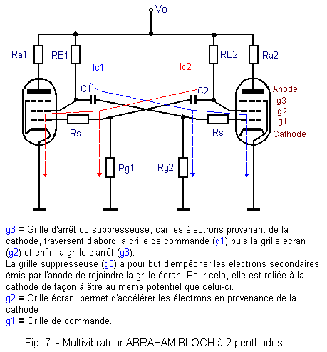
To overcome this disadvantage, we can use penthodes tubes.
The charge of the capacitors C1 and C2 is no longer made through the anode resistances but through the screen resistors RE1 and RE2.
Since there is no more load by Ra1 and Ra2, the rising edges are practically rectilinear and no longer exponential.
Figure 7 shows a multivibrator equipped with two penthodes
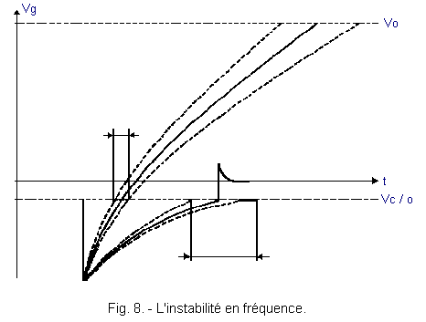
Despite all the improvements made to the ABRAHAM BLOCH multivibrator, this one still presents a major defect :the instability in frequency.
The instability is due to the angle of the exponential rise of the gate voltage, with the line representing the cut-off voltage of the tube (Figure 8).
When the gate resistors are connected to ground, the exponential rise is towards the potential 0.
A small external variation causes the cut-off line to cut off earlier or later and causes large differences in frequency.
By connecting the gate resistors directly to the high voltage, the discharge circuit passes through the high voltage source and the exponential rise is in the direction of the high voltage Vo.
In this way, small external variations cause only small displacements of the cutoff point between the gate voltage and the line representing the cut-off voltage.
With this means, the stability of the whole is significantly improved.
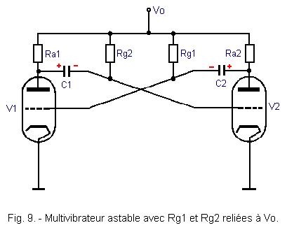
Figure 9 shows an astable multivibrator, whose gate leakage resistors Rg1 and Rg2 are connected to the high voltage.
With this assembly, it is necessary to rethink the value of the elements, because the gate resistances Rg1 and Rg2 must have very high values, so that the gate potentials close to 0 volt.
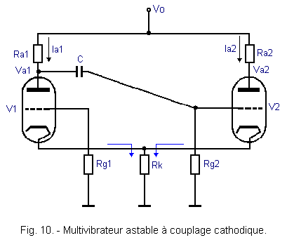
3. - ASTABLE MULTIVIBRATOR WITH CATHODE COUPLING
This multivibrator is an astable and asymmetrical assembly.
The cathodes are united and connected to the ground by a polarization resistor Rk.
The schematic diagram of such a circuit is shown in Figure 10.
As soon as the high voltage is applied, the two triodes start driving, but the voltage drop of Va1 is transmitted to Rg2 by the capacitor C.
Since this variation is negative, we have a negative voltage on the V2 grid.
Very quickly, we get V2 blocked and V1 driving normally.
Simultaneously with this, capacitor C charges at high voltage across Ra1 and Rg2.
The gate of V1 is connected to the ground by a low value resistor and is practically grounded.
V1 leading, the capacitor C can exponentially discharge through the internal resistance of V1 and the resistance Rg2.
The current in V1 creates a voltage drop Vk in the resistor Rk and the cathodes are at a positive potential with respect to the ground.
As soon as Vg2 reaches the critical point of cut-off, a current is established in V2. The voltage drop in Rk becomes more positive and that is to say that the grid of V1 becomes more negative.
The current Ia1 in V1 decreases and the voltage Va1 increases.
This variation of the potential of Va1 is plotted on the gate of V2 through capacitor C, which further increases the current in V2 ; hence, further increase of Vk and faster decrease of the current in V1.
The effect being cumulative, V1 is quickly blocked while V2 leads to the maximum.
As soon as V1 is blocked (Va1 = Vo), the capacitor C is charged through Ra1 and Rg2. When this charge is complete, the gate of V2 is brought back to the potential of the mass ; the current in V2 then decreases slightly, which causes a decrease in the cathode voltage.
This reduction is sufficient to unlock the V1 tube that starts driving again.
Current Ia1 creates a voltage drop in Ra1, which is plotted on the grid of V2. The cumulative action quickly brings V2 to the prohibition and V1 to the maximum conduction.
Capacitor C can discharge through V1 and Rg2 and a new cycle begins again.
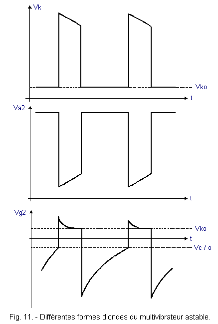
In Figure 11, you will find the different waveforms present in the circuit that we have just described.
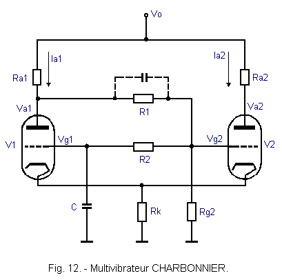
This cathodic coupling multivibrator, represented in Figure 12, is a variant of the previous assembly.
The gate voltage of the tube V1 appears across the capacitor C, which forms with R2 a long RC.
As soon as the high voltage is applied, the two tubes begin to drive. But the gate of V2 is brought to a positive potential by the resistor bridge Ra1, R1 and Rg2 placed between the high voltage and the ground.
The tube V2 thus leads much more than the tube V1.
The gate of V1 is at a potential close to ground (the capacitor C has received no charge) and the current Ia2 creates a positive voltage across Rk.
Very quickly, we get V1 blocked and V2 driving heavily.
The positive voltage Vg2 appearing across the terminals of Rg2 is also applied across the RC circuit formed by the resistor R2 and the capacitor C.
Capacitor C will thus slowly charge through R2 at voltage Vg2. As soon as its armature connected to the gate of V1 is at a positive potential corresponding to the unblocking voltage of the tube V1 (Vg1 = Vk - V cut-off), the latter begins to conduct and its anode voltage Va1 decreases.
The decrease of Va1 causes a decrease of Vg2 (thanks to the resistors R1 and Rg2) sufficient to block the tube V2.
The voltage drop of Vg2 is also present across R2. Capacitor C can therefore be discharged through R2 and Rg2. (It should be noted that the discharge can not be made through the gate-cathode space of V1 and Rk, because the voltage Vk is higher than the voltage Vg1).
The voltage Vg1 decreasing exponentially, the tube V1 leads less and less and the voltage Vk is less and less important.
After a certain time, the gate voltage Vg1 is no longer sufficient to maintain the tube in conduction and the latter is blocked. At the same time, the voltage Va1 goes back to the potential Vo.
This positive variation is transmitted by the resistance bridge R1 and Rg2 to the gate of V2.
The increase of the gate potential and the low cathode polarization voltage make the V2 tube very easy to unlock.
The current Ia2, very important, causes a high voltage drop in Rk which keeps the tube V1 to prohibition.
The edit has returned to the starting conditions (V2 leads, V1 blocked) and a new cycle can start again.
The signal collected on the anode of V1 has deformations, due to the fact that the current Ia1 follows the variations of the gate voltage Vg1.
On the other hand, the signal collected on the anode of V2 is perfectly rectangular.
The frequency of the square wave delivered by a CHARBONNIER multivibrator is relatively stable and largely determined by the time constant of the circuit R2 C.
By design, this assembly can only provide perfectly symmetrical slots (cyclic ratio equal to 1).
To transmit more easily the variations of the anode voltage Va1 on the control gate of V2, the assembly can be improved by connecting a small capacitor across R1. This capacitor is marked in dotted line in Figure 12.


 Definition of a square wave
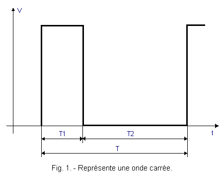
 Click here for the next lesson or in the summary provided for this purpose.
 Top of page
 Next Page