Study of the MM 74C163 Circuit as Programmable Divider :
8. - SEVENTH EXPERIENCE : USING THE MM 74C163 CIRCUIT AS A PROGRAMMABLE DIVIDER
In the previous experiment, the CARRY output was permanently at the L level, so it was not possible to exploit it.
However, if you want to mount several cascading counters, it is necessary to connect the CARRY output of a counter to the next counter. Indeed, as soon as a counter reaches its maximum capacity, the CARRY output goes high and allows the validation of the next counter. The latter will take into account the clock signal that will follow.
In this experiment, you will realize a variable module counter, programmable and using the CARRY output. In addition, the LOAD input is used to allow programming.
8. 1. - REALIZATION OF THE CIRCUIT
a) Remove all links related to the previous experiment. Leave in place the integrated circuits MM 74C163 and MM 74C00.
b) Perform the connections shown in Figure 21-a. The electrical diagram of the assembly made is given in Figure 21-b. The signal present on the CARRY output is the opposite of that present on the LOAD input.
8. 2. - OPERATING TESTS
a) Turn the switches to the 0 position and turn on the digilab.
b) Hold down P1 and press P0. The four LEDs are off. The counter is reset.
c) Release P1 and set switch SW0 to position 0,SW1 to 1,SW2 to 0 and SW3 to 1.
The counter is thus prepositioned at 10.
d) Press P0 fifteen times. The counter successively changes from state 0 to state 15.
At state 15, the CARRY output goes to the H level and the LOAD input goes to the L level.
e) Press P0 again.
LEDs L1 and L3 are lit and LEDs L0 and L2 are off.
The counter is thus set to the state 10. Indeed, the LOAD input was at the L level and the counter was prepositioned in the state where the four inputs IN1, IN2, IN3 and IN4 were located.
f) Press P0 repeatedly. You notice that the counter does not take any of the states between 0 and 9 but only those between 10 and 15. It is indeed a modulo 6 counter.
This appears in Figure 22.
g) Move the link from the CLOCK input of the P0
contact to the CP1 contact.
In addition, set the clock generator digilab on the frequency 1 Hz.
This setup works like a divider by 6. You can see that the L7 LED lights up periodically every six seconds.
h) Repeat the experiment by changing the logical combination of the four inputs IN1, IN2, IN3 and IN4.
You observe that the ignition frequency of the L7 LED is directly a function of this combination.
In conclusion, this experiment shows you how to use the MM 74C163 circuit as a divider and programmable counter.
To obtain the module of the realized counter, it suffices to subtract from the maximum number of states of the integrated circuit the number displayed on the inputs IN1, IN2, IN3 and IN4.
In this experiment, the module was worth 6 (16 - 10 = 6).
This counter is programmable since it suffices to put the desired combination on the four inputs IN1, IN2, IN3 and IN4.
By cons, compared to the previous experience, this counter modulo 6 does not go through the state 0.
Practically, this is the type of application that allows you to choose one or the other of the two proposed fixtures.
9. - EIGHTH EXPERIMENT : STUDY OF A SYNCHRONOUS
METER / DECOMPERSOR (UP / DOWN) IN FOUR FLOORS
The different counters examined up to now have an increasing counting mode.
At the level of the state diagram, the progression from one state to the next is always in the same direction.
There are also down-counters, the progression of which is in the opposite direction.
The same integrated circuit can operate in counting mode or in counting mode.
An example of an application is the determination of the number of people in a room.
For that, it is enough to use two photocells detecting the direction of crossing of the door.
When a person enters, the counter is incremented by one unit, that is, it immediately goes to the next number.
When a person goes out, the counter is decremented by one unit.
The counter goes to the next lower number. So it is possible to know at any time the exact number of people in the room.
With this new experience, you will check the operation of a new integrated circuit, the MM 74C193.
It is a four stages synchronous down-counter. This one is quite similar to MM 74C163.
It has, indeed, a LOAD input and four inputs IN1, IN2, IN3 and IN4 allowing the prepositioning.
Figure 23 illustrates the logic diagram of this circuit and Figure 24 its pinout.
As you see in Figure 23, this counter consists of four type D flip-flops mounted as a divide by 2 (the input T = Toggle is the clock input), that is, they change state logic at each clock pulse arriving at the input T.
This is the editing proposed in the first experiment where a type D flip-flop is mounted as a divider by 2.
The four outputs are always indicated Q1, Q2, Q3 and Q4.
The CLEAR entry is used to force the counter to zero. She is active at level H.
The LOAD input is active at the L level. These two inputs are asynchronous, therefore active independently of the clock.
This circuit also has two inputs called COUNT UP and COUNT DOWN.
They are the ones that make it possible to use the integrated circuit in counting mode or in countdown mode.
In count mode, the clock is applied to the COUNT UP input and the COUNT DOWN input is wired to logic H.
When the counter is at 15 and the COUNT UP entry at L, the CARRY output goes to L level.
In downcount mode, it is the COUNT DOWN input that receives the clock signal, while the COUNT UP input is wired to logic H.
When the counter is at 0 and the COUNT DOWN input at the L level, the BORROW (retenue) output goes to the L level.
This output is used when multiple counters are cascaded.
9. 1. - REALIZATION OF THE CIRCUIT
a) Remove the links relating to the previous experiment as well as the integrated circuits mounted on the matrix.
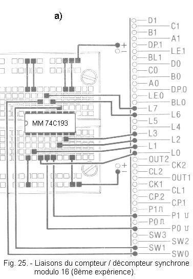
b) Insert the integrated circuit MM 74C193 on the matrix and make the connections shown in Figure 25-a.
The electrical diagram of the realized circuit is given in Figure 25-b.
9. 2. - OPERATING TEST
a) Put SW0 on position 0 and SW1 on position 1.
b) Turn on the digilab.
The LEDs L6 and L7 are lit.
c) Put SW0 on position 1.
LEDs L0, L1, L2 and L3 are off. LEDs L7 and L6 remain on. The counter is at 0.
d) Put SW0 on the 0 position.
The CLEAR entry is therefore inactive. Momentarily put SW1 on position 0 then go back to position 1. Thus, you activate the entry LOAD.LEDs L0, L2 and L3 are lit, while L1 remains off.
Inputs IN1, IN2, IN3 and IN4 are at logic states corresponding to state 13.
IN1 is in the high state (1)
IN2 is in the low state (0)
IN3 is in the high state (1)
IN4 is in the high state (1).
As long as you do not press the P0 and P1 buttons, the COUNT UP and COUNT DOWN inputs are at H.
It will be sufficient to press P1 or P0 according to the mode (counting or down counting) desired.
The active front will take place when you release the selected button.
e) Press P1 then release this button. The counter has gone to state 14.
f) Press P1 again and release it. The counter goes to state 15 ;the four LEDs L0, L1, L2 and L3 light up.
g)Press and hold P1 in this position. LED L6 corresponding to the CARRY output goes out. This confirms that the meter has reached its maximum capacity.
h) Release the P1 button. The counter goes to state 0. LEDs L0, L1, L2 and L3 are off. LED L6 turns on again.
i) Press P1 twice again. The counter changes to state 2 (L0 off, L1 on, L2 off, L3 off).
j) Press P0 once and release it. The counter goes to state 1. Press P0 again and release it. The counter goes to state 0.
k)Press P0 and hold it as well. LED L7 goes out. This confirms that the counter has reached state 0.
l)Release P0. The meter goes to state 15 and the LED L7 turns back on. If you continue to press P0, the counter is decremented by one unit at each pulse.
You can alternatively press P0 or P1 repeatedly.
In one case, you decrement the counter, in the other case, you increment it.
To conclude, it is possible to give the essential characteristics of this circuit MM 74C193 :
the CLEAR input is active at the H level and has priority over all other inputs.
when a level L is applied to the LOAD input, the counter goes to the state corresponding to inputs IN1, IN2, IN3 and IN4 if the entry CLEAR is at level L.
the CLEAR and LOAD entries are asynchronous.
a transition from L to H on the COUNT UP entry determines an incrementation of the counter.
a transition from L to H on the COUNT DOWN input determines a decrement of the counter.
the CARRY output goes to L level when the COUNT UP entry returns to L level and the counter is in state 15.
At the next transition from L to H of the COUNT UP entry, the CARRY output returns to the H level, thereby generating a carry pulse for the next possible counter.
the BORROW output goes to the L level when the COUNT DOWN entry returns to the L level and the counter is in the 0 state.
At the next transition from L to H of the COUNT DOWN entry. The output BORROW returns to the level H, thus generating a pulse which makes it possible to decrement of one unit the following counter.
It is possible to mount multiple meters in cascade.
Simply connect the COUNT UP and COUNT DOWN inputs of each counter to the CARRY and BORROW outputs of the previous counter. This is shown in Figure 26.
10. - NINTH EXPERIENCE : ELECTRONIC
GAME WITH A COUNTER
In order to become familiar with the use of counters, you will now make a montage that simulates a game of dice. The goal of this game is to guess the state on which a counter stops.
10. 1. - REALIZATION OF THE CIRCUIT
a) Remove the connections related to the previous experiment and leave in place the integrated circuit MM 74C193.
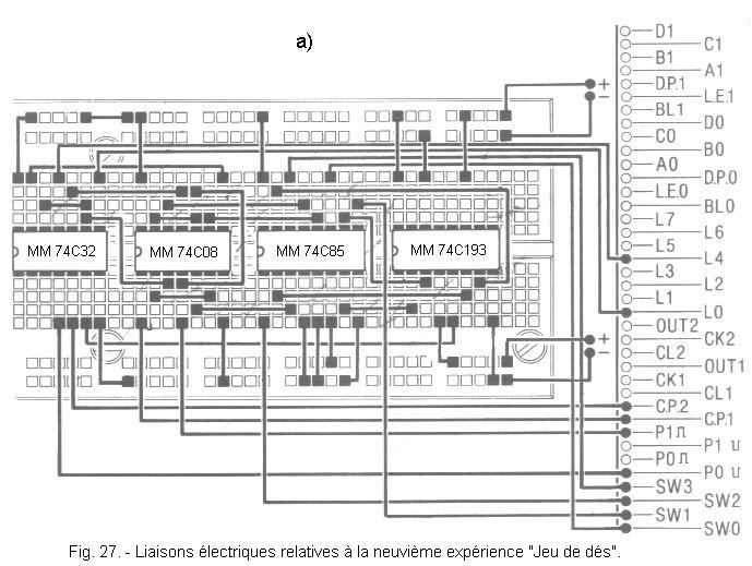
b) Insert the integrated circuits MM 74C85, MM 74C08 and MM 74C32 on the matrix, as shown in Figure 27-a and make the connections illustrated by this same figure.
Check that the wiring is in accordance with the wiring diagram in Figure 27-b.
c) Arrange the first clock generator on the frequency of 1 Hz and the second clock generator on the frequency of 1 kHz.
10. 2. - OPERATING TESTS
a) Turn on the digilab.
b) Press the P0 button for a while : the 1 kHz clock signal increments the counter.
The latter therefore changes state a thousand times a second. Then release P0. Thus, the counter stops randomly on one of its 16 possible states.
c) Position the four switches in the state where you assume the meter has stopped.
For example,
if you think the counter stopped at state 10, set SW0 to 0, SW1 to 1, SW2 to 0, and SW3 to 1 (see the table in Figure 11).
d) Press P1 : if the combination formed by the four switches represents a number smaller than that determined by the state of the counter, the LED L0 will light up.
This happens for example if the counter has stopped in the state representative of the number 10 and you have dialed a number between 0 and 9.
If, on the other hand, the number you have dialed is higher than that given by the counter, the LED L4 will light up.
This happens for example if the counter has stopped in the state representing 10 and you have chosen a combination between 11 and 15.
If finally the chosen state is equal to that of the counter, the two LEDs L0 and L4 will flash at the frequency of 1 Hz.
You can continue the experiment several times in a row.
e) Turn off the digilab.
Experienced editing works like this :
Pressing P0 unlocks the OR gate (identified by the letter "a" in Figure 27-b). Thus, the 1 kHz clock signal increments the counter. This therefore counts the pulses and stops when P0 is released. The counting frequency being high, we can not predict the state where the counter will stop.
The circuit MM 74C85 compares the state of the counter with the state composed on the four switches.
Pressing P1 unlocks the first three AND gates. Thus, the output of each of these doors copies the level present on the outputs of the comparator.
If the output A > B is at level H, it forces the OR gate marked with the letter "b" to level H and the LED L0 lights up.
If the output A < B is at level H, it forces the OR gate marked with the letter "c" to level H and the LED L4 lights up.
If, on the other hand, the output A = B is at the level H, the AND gate marked by the letter "d" validates the signal of frequency 1 Hz.The two doors OR "b" and "c" not being forced at the level H logic, the 1 Hz frequency signal is therefore found at the exit of these doors.
Both LEDs L0 and L4 flash at the same frequency of 1 Hz.
Thus ends this practice in which you have experienced the operation of asynchronous and synchronous counters. These have their outputs coded in pure binary.
In the next practice, you will see how to translate this binary code into a decimal code.


 Study of a synchronous up / down counter (UP / DOWN) with four stages MM 74C193
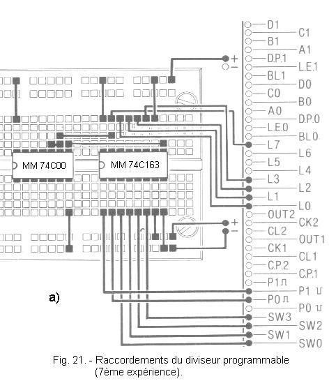
 Click here for the next lesson or in the summary provided for this purpose.
 Top of page
 Next Page