In this practice, we will discuss three interrelated topics : codes, decoders and displays.
Codes are systems for representing information in the form of electrical signals.
Decoders are circuits that convert coded information to make it more explicit.
The displays are devices for displaying logical information.
1. - THE CODES
1. 1. - INTRODUCTION
"The secret agent opened the letter, deciphered it, then destroyed it, the instructions were very clear ...".
How often have you read this kind of sentence or seen a movie scene reproducing this fact !
The secret agent was able to decipher the message because he knew the code with which it was written.
Indeed, every language is a code. For example, a conversation that takes place between two Russians is incomprehensible to most French people, although the two interlocutors understand each other since they speak the same language.
From these examples, it is possible to deduce the following rule :
a code, to be valid, must be known as well of the one who emits it as of that which receives it.
In digital circuits also, the electrical signals representing the information to be processed are codified.
It is therefore very important to know the code used since this "language" allows communication between digital circuits.
The codes are numerous, but they all rest on the fact that an electrical signal in digital electronics can have only two logical levels ; namely a level L or a level H.
The set of codes therefore uses the numbers 0 and 1 which correspond to the two logical levels L and H.
In this practice, you will examine numeric codes, that is, those used to represent numbers.
Those relating to the transmission of letters or messages of the type used by the telegraph will not be treated.
Take the following components from all equipment in your possession.
two resistors of 220 W
- tolerance 5 %
two resistors of 4700 W
- tolerance 5 %
a resistor of 1 MW
- tolerance 5%
a tantalum electrolytic capacitor of 1 µF - 10 V
a diode 1N 4148
two transistors BC 238 (or equivalent type)
two TIL 311 displays
an integrated circuit MM 74C00
an integrated circuit MM 74C02
an integrated circuit MM 74C08
an integrated circuit MM 74C42
an integrated circuit MM 74C154
an integrated circuit MM 74C163
an integrated circuit MM 74C193
3. - FIRST EXPERIENCE : REVIEWING THE CODE
USED BY A COUNTER
In practice 9, you looked at different types of meters. Each combination of output levels corresponds to a specific state of the counter. This state allows you to know the number of events totalized by the counter.
The numbers assigned to these different states could result from a very arbitrary choice ; in fact, it is not so because these numbers are relative to a well-defined code.
To verify this fact, you will use the synchronous counter modulo 16 type MM 74C163.
3. 1. - REALIZATION OF THE CIRCUIT
a) Remove from the array and connector group all links and components related to the last experiment.
b) Turn the digilab switch to the "OFF" position and plug the plug into the power outlet.
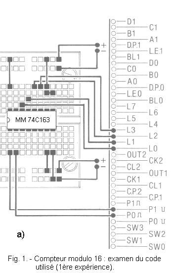
c) Insert the integrated circuit MM 74C163 into the matrix and make the connections as shown in Figure 1-a.
The electrical diagram of the assembly is shown in Figure 1-b.
The meter is wired as follows :
The inputs CET and CEP are at level H, the counter is thus validated.
The LOAD input is at level H, therefore inactive ; the inputs IN1, IN2, IN3 and IN4 can not play any role.
The clock is connected to the contact
P0; each pulse on the button P0 will therefore advance the state of the counter.
The entry CLEAR is connected to the
contact P1
; at rest, the CLEAR input will be inactive. Pressing P1 then P0 (the CLEAR input is synchronous), the counter will be set to zero.
The four outputs Q1, Q2, Q3 and Q4 are respectively connected to the four LEDs L0, L1, L2 and L3.
3. 2. - OPERATING TEST
a) Turn on the digilab.
The state of the four outputs is random.
b) Press P1 then P0 while holding down both buttons for a short time.
The counter is prepositioned to zero.
c) Press P0,LED L0 lights up.
d) Press P0 repeatedly. Observe the indication of the LEDs each time.
Remember that a lit LED corresponds to a level H and an extinct LED corresponds to a level L.
Note the level of the outputs each time. You get the table from Figure 2.
Fig. 2. - Levels of the voltages of the four outputs obtained by pressing P0.
Number of pressures on P0
Q4
Q3
Q2
Q1
0
L
L
L
L
1
L
L
L
H
2
L
L
H
L
3
L
L
H
H
4
L
H
L
L
5
L
H
L
H
6
L
H
H
L
7
L
H
H
H
8
H
L
L
L
9
H
L
L
H
10
H
L
H
L
11
H
L
H
H
12
H
H
L
L
13
H
H
L
H
14
H
H
H
L
15
H
H
H
H
e) Turn off the digilab. So far, you have not seen anything new that you have not seen in the previous practice.
However, you will highlight the code used by this counter.
For that, you will replace the level L by the number 0 and the level H by the number 1.
You get the table from Figure 3.
Fig. 3. - Table obtained from the table of Figure 2 by replacing the letters H and L respectively by the numbers 1 and 0.
Number of pressures on P0
Q4
Q3
Q2
Q1
0
0
0
0
0
1
0
0
0
1
2
0
0
1
0
3
0
0
1
1
4
0
1
0
0
5
0
1
0
1
6
0
1
1
0
7
0
1
1
1
8
1
0
0
0
9
1
0
0
1
10
1
0
1
0
11
1
0
1
1
12
1
1
0
0
13
1
1
0
1
14
1
1
1
0
15
1
1
1
1
Observe this table carefully, line by line.
It appears to you that for each number of pressures on P0 (which is a decimal number), is written in correspondence the same number in binary code.
The most significant digit (MSB) is Q4 and the least significant digit (LSB) is Q1.
Starting from the top of the table, we find :
00002
= 0 x 23 + 0 x 22 +
0 x 21 + 0 x 20
= 0 x 8 + 0 x 4 + 0 x 2 + 0 x 1 = 010
00012
= 0 x 23 + 0 x 22 +
0 x 21 + 1 x 20
= 0 x 8 + 0 x 4 + 0 x 2 + 1 x 1 = 110
00102
= 0 x 23 + 0 x 22 + 1 x 21 + 0 x 20
= 0 x 8 + 0 x 4 + 1 x 2 + 0 x 1 = 210
and so on until the number 1111 of the last line.
Remember that the conversion of a decimal number into a binary number is done by successive divisions.
For example, to convert the decimal number 12 to a binary number, proceed as follows :
The binary number is obtained by reading the remains from bottom to top, in this case :
1210
= 11002.
In conclusion, it appears that this counter uses the binary code.
With this experiment, it is enough to observe the state of the LEDs (on or off) to know the representation in binary code of the number of pulses arriving at the counter.
In Figure 4, the 16 possible combinations of this counter are represented by the corresponding state of the LEDs and the decimal number associated with this state.


 Numeric Codes
.gif)
 Click here for the next lesson or in the summary provided for this purpose
 Top of page
 Next Page