Studying a Synchronous "D Flip-flop" as a Modulo 2 Counter :
During this practice, you will experimentally verify the operation of the meters and dividers.
A counter allows to know the number of events occurring during a given period. A divider reduces in a given ratio the number of events that occur on the input of the divider.
The two functions, counting and division, are often performed by the same circuit. An analogy can be given by the clock of a steeple, shown in Figure 1. Indeed, the number of seconds elapsed is divided by 3 600.
Every 3600 seconds the chimes indicate that an hour has elapsed.
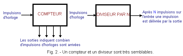
In digital electronics, the events are translated into pulses applied to the CLOCK input of the circuits concerned as illustrated in Figure 2.
The frequency of the output signal of a divider is always lower than that of the input signal. The ratio between the frequencies of the input and output signals is an integer N.
In the case of a counter, the logic state of the output (s) changes with each clock pulse.
Thus, the outputs provide information on the number of pulses applied to the clock input. In this way, the outputs make it possible to know the number of pulses arriving at the input.
The main features of a meter are :
his capacity
its module
Capacity is the largest number of events a counter can total ; a car odometer for example has a capacity of 99 999 kilometers.
The module, on the other hand, is the number of possible states of the counter, including the initial state. It is therefore equal to the increased capacity of one.
Thus, a car odometer has a module of : 99 999 + 1 = 100 000.
To realize the experiences of this practice, you will have to use the following integrated circuits :
MM 74C74 or equivalent
MM 74C175 or equivalent
MM 74C86 or equivalent
MM 74C08 or equivalent
MM 74C163 or equivalent
MM 74C00 or equivalent
MM 74C193 or equivalent
MM 74C85 or equivalent
MM 74C32 or equivalent
2. - FIRST EXPERIENCE : USE OF A SYNCHRONOUS "D"
ROCKER AS A MODULO 2 COUNTER
In this experiment, you will realize the simplest of the counters by using a D flip-flop wired in divider by 2.
The counting capacity of this very simple circuit is limited ; indeed, it counts only up to 1. It has a capacity of 1 and it is of module 2.
While very simple, this circuit is important because it is the basic element of higher capacity meters.
2. 1. - REALIZATION OF THE CIRCUIT
a) Remove from the matrix and contacts of the connector group all the connections and components related to the previous experiment.
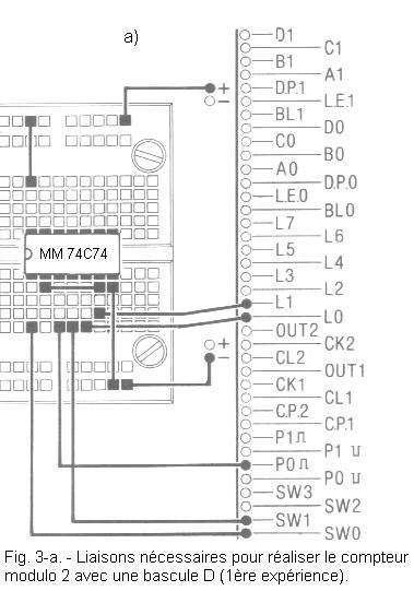
b) Take the integrated circuit MM 74C74 (double D flip-flop), insert it on the matrix in the position shown in Figure 3-a and make the indicated connections.
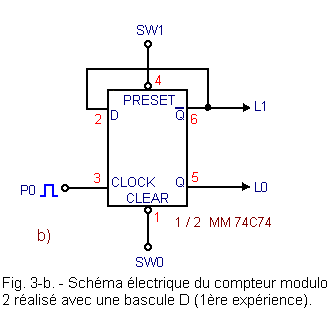
Figure 3-b shows the circuit diagram of the realized circuit
2. 2. - OPERATING TESTS
a) Place SW0 and SW1 on position 0, then insert the plug into the socket and turn on the digilab. You notice that LEDs L0 and L1 are off.
b) Now set SW1 to position 1 : thus, the PRESET input becomes inactive. The flip-flop is in state 0 (Q = 0 and = 1) since the entry CLEAR is active. This is confirmed by the fact that L0 is off and L1 is on.
c) Set SW0 to position 1, the CLEAR input becomes inactive as the PRESET input. The flip-flop is therefore no longer forced to any state and can therefore transfer at output Q the logic level present on the input D at each positive transition of the clock signal.
d) Then press the P0 button, the level H present on the input D is therefore transferred to the output Q, which you notice by observing the LED L0 on and the LED L1 off.
Indeed, the output Q has passed to the level H and the output
to the level L.
Thus, the circuit took into account a clock pulse and signaled it by an output state change Q.
e) Press P0 again ; L1 lights up and L0 goes out.
Indeed, the level L present on the input D has been transferred to output Q. The flip-flop has returned to the state 0 (Q = 0 and = 1).
This can be interpreted as saying that the meter has exceeded its capacity and has returned to its original state.
f) Switch the power switch to "OFF".
In summary, the circuit under review proves to be a capacity counter 1.
In fact, initially zeroed by means of the CLEAR input (output Q at state 0), it is able to signal a single pulse applied to its CLOCK input.
This event was indicated by the Q output which went from the L level to the H level. The counter therefore went to state 1.
Pressing P0 a second time, thus applying a second clock pulse, you have exceeded the capacity of the counter and it has returned to the initial 0 state.
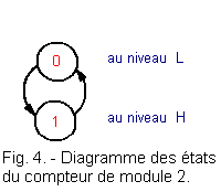
Since two pulses are sufficient for the counter to return to its initial state, the counter is of module 2.
The succession of states 0 and 1 of the counter can be represented by the state diagram of Figure 4. This shows that there are only two possible states.
The transition from one state to another of the counter occurs only when an active edge arrives at the CLOCK input.
3. - SECOND EXPERIENCE : USE OF A COUNTER AS FREQUENCY
DIVIDER
In this manipulation, you will continue the examination of the same circuit as that used in the previous experiment. This circuit will be examined not as a counter, but as a divider.
Previously, the flip-flop was used as a module counter 2. Now, it will be used to divide by 2 the frequency of the signal applied to the CLOCK input.
3. 1. - REALIZATION OF THE CIRCUIT
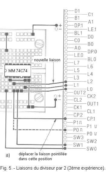
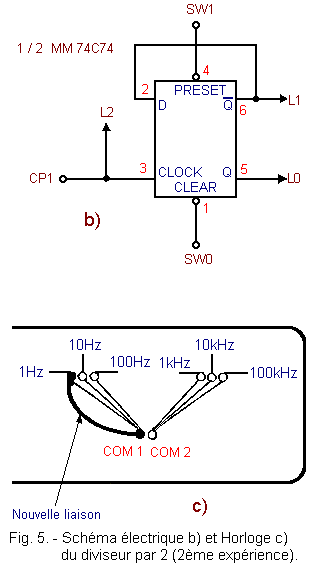
a) Disconnect the link connecting pin 3 of the integrated circuit MM 74C74 to the contact P0.
b) Connect pin 3 to contact CP1 and contact L2, as shown in Figure 5-a.
c) Place the first digilab clock generator on the 1 Hz frequency by connecting the COM 1 contact to the contact indicated by the 1 Hz marking as shown in Figure 5-c.
he circuit diagram of the realized circuit is shown in Figure 5-b.
3. 2. - OPERATING TESTS
a) Place SW0 on position 0 and SW1 on position 1.
b) turn on the digilab, you see that L2 flashes at a frequency of 1 Hz while L0 is off and L1 is on.
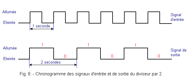
c) Put SW0 on position 1, you see that L0 turns on and off periodically. It stays on for one second, then stays off for the next second.
The period of the signal on the output Q is thus 2 seconds and the frequency of this signal is 1 / 2 Hz. L0 therefore flashes at a frequency 2 times smaller than that of L2.
In other words, the circuit divides by 2 the frequency of the signal present on the input CLOCK. Since the input signal at a frequency of 1 Hz, the output signal has a frequency of 0.5 Hz.
Figure 6 represents the succession of states 0 and 1 at the input and the corresponding changes in the state of the output.
As you can see, the Q output of the flip-flop only changes state at the rising edge of the clock signal. To obtain a complete cycle at the output, two complete cycles of the clock signal are required. The frequency of this signal is thus reduced by half.
The car odometer could be considered a divider if it generated for example a sound signal (or light) each time it indicates 00 000. Indeed, such a signal (assuming that the speed of the car is constant) would have a frequency 100 000 times smaller than that of the signal that advances the meter by one kilometer.


 Preparation of equipment
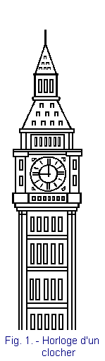
 Click here for the next lesson or in the summary provided for this purpose.
 Haut de page
 Next Page