Studying a Module 4 Counter Realized with Two Module 2 Counters :
4. - THIRD EXPERIENCE : EXAMINING A MODULE 4 COUNTER MADE WITH TWO MODULE 2 COUNTERS
It is not always enough to divide by 2 : for example, in digital watches, to obtain a high precision, we use a very stable quartz oscillator, operating at the frequency of 32 768 Hz. This basic frequency is then divided by a module counter 32 768, so as to obtain a frequency of 1 Hz.
This frequency corresponds to one pulse per second which will be used to control the seconds indicator device.
In addition to the seconds, the watch must also indicate the minutes.
It therefore uses a module counter 60 which totals 60 pulses of 1 second to obtain a pulse every minute.
A second module counter 60 then totals 60 pulses of 1 minute to give a pulse every hour.
In this experiment, we will not examine such high module counters, but we will increase the capacity of simple counters of the first two experiments to obtain a module counter 4.
4. 1. - REALIZATION OF THE CIRCUIT
a) Remove all the links relating to the previous experiment leaving the integrated circuit MM 74C74 on the matrix.
b) Perform the connections shown in Figure 7-a.
The electrical diagram of the realized circuit is given in Figure 7-b.
4. 2. - OPERATING TESTS
a) Put SW0 on position 0 and turn on the digilab : LEDs L0 and L1 are off, CLEAR inputs are active. Let us denote this state by state 0, so we can write :
State 0 = L0 off and L1 off
b) Set SW0 to position 1 : the two CLEAR inputs are no longer active.
c) Press P0 : L0 lights up and L1 remains off. Let us denote this state by state 1 :
State 1 = L0 on and L1 off
d) Press P0 again : L0 goes out and L1 lights up. Let us denote this state by state 2 :
State 2 = L0 off and L1 on
e) Press P0 for a third time : L0 lights up and L1 stays on. Let us denote this state by state 3 :
State 3 = L0 on and L1 on
f) Press once again P0 : L0 and L1 go out. The circuit has returned to the initial 0 state. This circuit is therefore able to count three pulses ; in the fourth, it returns to zero since its counting capacity has been exceeded.
g) Turn off the digilab.
h) Arrange the first digilab clock generator on the 1 Hz frequency.
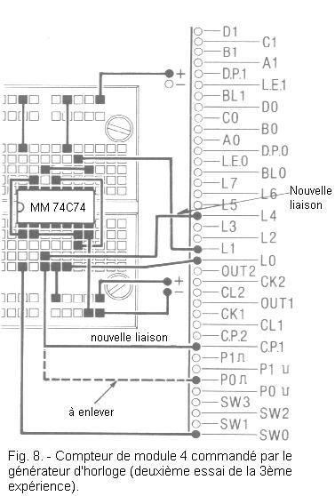
i) Remove from the contact P0
the end of the conductor coming from pin 3 of the integrated circuit MM 74C74 and insert it into the contact CP1 as indicated in Figure 8.
In this way you apply to the input CLOCK, either the signal provided by the button P0, but that generated by the oscillator wired on the frequency of 1 Hz and visualized by means of L4.
j) Connect the pin 3 of the integrated circuit MM 74C74 to the LED L4 as indicated by this same Figure 8.
k) Connect the power supply : L4 switches on and off at the rate of once per second ; L0 on the other hand, lights once every two seconds and L1 only once every four seconds.
As shown in the timing diagram of Figure 9, the circuit also functions as a divider.
At the output of the first flip-flop (pin 5), the clock signal is divided by 2 while at the output of the second flip-flop (pin 9), the latter is divided by 4.
l) Turn off the digilab.
As you can see, by connecting two module 2 counters in cascade, we obtain a module counter 4. The same circuit can, in addition, operate as a divider by 2 or 4 depending on whether we take the signal from exit of the first rocker or the second rocker.
By adding thereafter other counters of module 2, the capacity of the counter circuit is thus increased as well as of the divider circuit.
For example with three flip-flops, one can realize a divider by 8, with four flip-flops a divider by 16 and so on.
5. - FOURTH EXPERIMENT : REALIZING AND EXAMINING
A SYNCHRONOUS MODULE METER 16
The module counter 4 that you realized in the previous experiment is of asynchronous type.
Indeed, the two flip-flops which constitute it are controlled by two different clock signals. The clock signal of the first flip-flop comes from the oscillator at 1 Hz, while the clock signal of the second flip-flop is provided by the output
of the first flip-flop. Thus, the second stage of the meter switches only after the first stage has switched under the effect of a clock pulse.
If the meter is formed of several stages, it follows that each of them must wait for the switch of the previous to switch in turn.
If the switching of one stage was instantaneous, all the outputs of the meter would switch simultaneously.
In reality, this switching is done with a certain delay. The transfer time of one stage is therefore added with that of the next.
Therefore, between the moment the clock pulse arrives and the moment when the last flip-flop switches, a longer time elapses as the number of stages constituting the counter is high.
In some cases, this can be a disadvantage that can be avoided by using synchronous counters. Indeed, the latches of these counters are simultaneously controlled by the same clock signal. Thus, there is no tilting delay between the different stages.
In this experiment, you will examine a synchronous module counter 16 made by means of flip-flops and logic gates.
5. 1. - REALIZATION OF THE CIRCUIT
a) Remove the connections relating to the previous experiment as well as the integrated circuit MM 74C74.
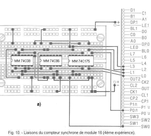
b) Insert the integrated circuits MM 74C175 (quadruple synchronous D flip-flops), MM 74C86 (quadruple OR - Exclusive), MM 74C08 (quadruple ET) and make the connections shown in Fgure 10-a.
The electrical diagram of the realized circuit is given in Figure 10-b. The inputs CLOCK and CLEAR are common to the four flip-flops, and the four outputs Q1, Q2, Q3 and Q4 respectively control the LEDs L0, L1, L2 and L3.
5. 2. - OPERATING TESTS
a) Put SW0 on the position 0 and turn on the digilab : the four LEDs L0, L1, L2 and L3 are off, the entry CLEAR being active.
b) Set SW0 to position 1 : the CLEAR input is now inactive and all four LEDs remain off. Let us denote this state of the outputs by state 0.
State
0 : L3 extinguished (Q4 at L level)
L2 extinguished (Q3 at L level)
L1 extinguished (Q2 at L level)
L0 extinguished (Q1 at L level)
c) Now press P0 : L0 lights up while the other LEDs remain off. Let us denote this state by state 1.
State 1
: L3 extinguished (Q4 at L level)
L2 extinguished (Q3 at L level)
L1 extinguished (Q2 at L level)
L0 on (Q1 on level H)
d) Continue to activate P0 and note the states of the outputs after each press on P0 : you obtain the table of Figure 11.
(Return to the game of electronics)
The timing diagram of Figure 12 makes it possible to know the levels present on the outputs Q1, Q2, Q3 and Q4 as a function of the number of pulses applied to the clock input.
You notice that there are 16 different states rated from 0 to 15.
After the sixteenth clock pulse the circuit returns to the initial state 0, its counting capacity being exceeded.
The realized counter therefore has a capacity of 15 and a module of 16.
e) Turn off the digilab.
The realized counter has the advantage of being synchronous.
Indeed, the four latches that compose it are controlled by the same clock signal ; they therefore switch at the same instant.
This can not be verified in practice because special measuring devices are required.
Indeed, the switching time of a flip-flop is of the order of ten millionths of a second.
The table in Figure 11 (see above) gives interesting indications for using the meter.
It is enough to observe the state of the four LEDs to know the number of pulses arriving at the counter input.
If, for example, the L3 and L2 LEDs are lit and the L1 and L0 LEDs are off, it can be seen immediately in the table that twelve pulses have reached the CLOCK input.
The counter under examination gives the result of counting in binary code (HHLL = 11002 = 12 in decimal).


 Realization and Examination of a Module 16 Synchronous Counter
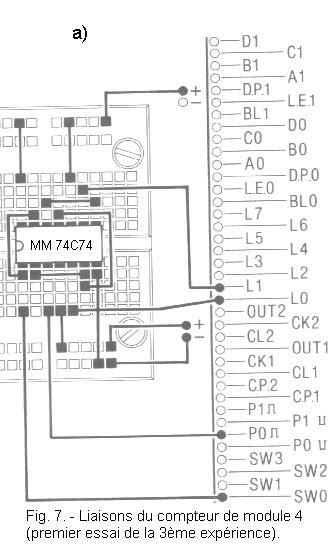
 Click here for the next lesson or in the summary provided for this purpose.
 Top of page
 Next Page