3. 5. - MOUNTING THE TRANSFORMER AND ENDING THE POWER WIRING
The transformer consists of an assembly of metal sheets on which are arranged the primary winding and the secondary winding. The 220 volts mains voltage is applied to the primary winding, the secondary winding is connected to the bridge rectifier.
Figure 16-a shows you the transformer.
The output of the primary winding is constituted by the two black wires, that of the secondary winding by the two red wires. Figure 16-b shows the circuit diagram of the transformer.
The secondary winding consists of a copper wire covered with an insulating enamel layer.
You must therefore follow the instructions below :
a) Carefully remove the insulating enamel covering the ends of the two wires of the secondary winding. Use sandpaper or a knife
b) Etam the ends of the primary and secondary wires.
c) Check the ohmmeter for continuity of the primary winding and the secondary winding. Place the controller on W
x 10.
Put the two test tips in contact with the two red wires. The ohmmeter indicates a very low value, close to zero. If this is not the case, you must scratch the enamel that may have remained and tin again.
Do the same for the two primary black wires. You find a value between 50
W and
90 W. If the needle does not deviate, the winding of the primary is cut off and the transformer defective.
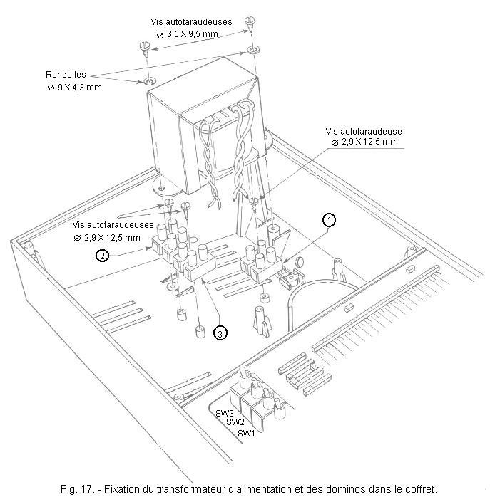
d) Place the transformer in the cabinet of the digilab in the position shown in Figure 17 and fix it with two self-tapping screws 3.5 x 9.5 mm by inserting two washers Ø 9 x 4.3 mm.
e) Fix in the positions indicated, always in figure 17 the three terminal blocks of two dominos marked by the numbers ,
and
by means of three self-tapping screws of 2,9 x 12,5 mm.
You will now prepare the power cord.
CAUTION: In some cases the power cord is already equipped with a power outlet. Do not take into account the mounting of the plug described below.
f) Strip off both ends A and B of the power cord as shown in Figure 18 and twist strands exposed.
g) Connect the A end of the power cord to the mains plug as shown in Figure 19.
Etame in advance the three wires of the end A of the power cord. The yellow and green wire is the ground wire. It is connected to the central terminal.
h) Etame the three wires at the B end of the power cord, and insert that end into the hole on the back of the cabinet. As shown in Figure 20, attach the two shortest wires in the .
terminal block. The yellow and green wire remains free for now.
i) Secure the power cable with the cable clamp on the bottom of the cabinet.
j) Twist the two black primary wires between them and connect them to the two dominos of the
terminal (figure 20).
k) Twist the two red wires of the secondary and connect them to the two dominos of the terminal .
l) Desolder the two alligator clips from the red and black conductors of the power cord of the printed circuit board. Take the three-pin female connector and, after orienting it as shown in Figure 21, solder the black conductor to the center pin 2 and the red conductor to the side pin 3. Just put the amount of tin needed to welding.
m) Insert the three pins of the female connector fully into their respective slots until they lock (Figure 21).
n) Referring to Figure 22, connect the two twisted black wires from the switch to the free terminals of the terminal block 2 dominoes.
Connect the two ends of the green twist to the free terminals of terminal block 3 and the two red conductors from the rectifier to the free terminals of terminal block 1. Do not yet insert the female connector into the male connector attached to the power supply circuit.
o) Unscrew the nut securing the die as shown in Figure 22 and lock with it an earth lug by inserting between the latter and the metal panel a fan washer. Then solder the end of the yellow and green ground wire from the power cord to the ground lug.
The assembly of the power supply is thus finished and you can proceed to the tests.
Before definitively attaching the metal panel to the enclosure, you must perform a preliminary voltage check of the supply circuit.
At certain points of the circuit, the mains voltage is present. Also, you must perform these tests with great care and caution.
The voltage of 220 volts is present at the following points :
dominoes of terminal blocks 2 and 3
terminals of the fuse holder
switch terminals
Make sure once again the good quality of the welds at these different connection points. Perform the following checks :
a) Place the panel next to the cabinet in the position shown in Figure 22 and set the power switch to the opposite position to the "OFF" position.
b) Insert the mains plug into a socket of the 220 volts network and with the controller arranged for the 30 volts AC voltage measurement, measure the AC voltage supplied by the secondary of the transformer, by putting the two test points on the two screws dominoes of the terminal block 1.
You must find a voltage between 8 and 10 volts. If you find zero voltage, remove the plug from the power outlet. Then check again the connections made on the power cord and terminals 1, 2 and 3 and control the transformer again with the ohmmeter controller.
c) Arrange the controller for 30 volt DC voltage measurement and check the voltage between the red and black wire clamp sockets. It must be 5 volts. Also make sure that the LED is on. If you find a voltage very different from 5 volts, check the entire assembly. If the voltage is normal but the LED is off, check the resistance R1 and the different connections with the LED.
d) If the whole control is good, disconnect the plug from the mains socket. The LED remains on for a few seconds because the electrolytic capacitor C1 takes a while to discharge. Once the LED is off, connect the male connector with the female connector attached to the power supply. Place the front panel on the cabinet without attaching it.
e) Reconnect the plug to the power outlet and check the voltage between the "+" and "-" terminals of the connector group. If this voltage is zero or reversed, review the mounting of the two male and female three pin connectors.
f) If this voltage is correct, disconnect the mains plug and turn the switch to "OFF". Permanently attach the front of the digilab with the four self-tapping screws.
Now,
you can continue with the montages proposed below. All these fixtures will be powered with this regulated 5 volts power supply.


 Power test
 Click here for the next lesson or in the summary provided for this purpose.
 Top of page
 Next Page