Review of a "CD 4528" Retrofit Monostable Integrated Circuit :
7. - SIXTH EXPERIMENT : OPERATING TEST OF A RELEASABLE MONOSTABLE
As you learned in Theory 6 (digital electronics), monostables are divided into "no retriggerable" and "retriggerable". They are classified in one or the other category according to their behavior in relation to the periodicity of the control pulses.
If, after having sent a first pulse to the input of a retriggerable monostable, a second pulse is applied before the output of the monostable is complete, the latter is extended by a time equal to that elapsed between the first and the last pulse. the second control pulse.
On the other hand, a monostable "no retriggerable" is completely insensitive to a second control pulse, as long as it has not returned to its state of rest.
The different operation of these two types of monostable is highlighted in the timing diagrams of Figure 10. Depending on the applications, it may be useful to exploit the specific characteristics of one or the other circuit.
a) Disconnect the power supply and remove all components and connections related to the previous experiment.
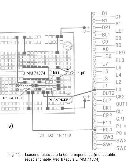
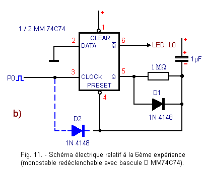
b) Insert on the matrix the integrated circuit MM 74C74 in the position indicated by Figure 11-a and realize the circuit illustrated by this Figure, by using a resistance of 1 MΩ, a capacitor of 1 µF and a 1N 4148 diode or its equivalent.
For the moment, do not put the diode D2 (1N 4148) and do not make the connections appearing in dashed lines on this figure.
You have thus realized the circuit of Figure 11-b ; it is a monostable "no retriggerable" operating in a manner quite similar to that of the third experiment. In this case, the PRESET input is used instead of the CLEAR input and for this reason the links are a bit different.
7. 2. - OPERATING TESTS
a) Connect the power supply : LED L0 will be off or stay on for a short time ; the circuit is then ready for testing.
b) Now activate the P0 button : the circuit operates in monostable mode just like the circuit of the third experiment, the LED L0 lights up for about 1 second.
c) Press the P0 button once for L0 to turn on, then press P0 once or more before L0 turns off. You see that the result is the same, that is to say that L0 remains lit during the same time of 1 second.
d) Insert diode D2 (1N 4148) into the matrix and make the connections shown in dotted lines in Figure 11-a or 11-b.
e) Press the P0 button and while the L0 LED is lit, press the P0 button again.
The L0 LED remains on for more than one second, which means that the monostable output pulse has been extended by one second when the P0 button was pressed a second time.
f) Press button P0 several times while LED L0 is lit.
You notice that it stays lit all the time you continue to press and release the P0 button as long as the rate is fast enough, that is, more than once a second. This occurs because each time a control pulse occurs on the monostable input, the capacitor is discharged through the diode connected to the CLOCK input ; as a result, the voltage across the capacitor can not reach the value necessary for the PRESET input to determine the state change of the flip-flop and terminate the output pulse.
8. - SEVENTH EXPERIENCE : EXAMINATION OF AN INTEGRATED MONOSTABLE CIRCUIT REDECLENCHABLE
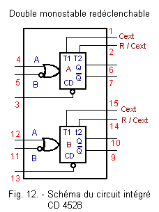
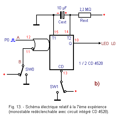
With this manipulation, you will check the operation of the integrated circuit CD 4528 containing two monostable "redeclenchables" having identical characteristics.
As you can see in the diagram of Figure 12, each monostable has three entries identified by the letters A, B and CD ; A and B are the control inputs, CD being the reset input (CLEAR).
This integrated circuit also requires for each monostable resistor Rext and external capacitor Cext, as the MM 74C221 seen previously.
However, unlike this, the duration of the output pulse CD 4528 is obtained by multiplying the product Rext X Cext by a coefficient K which also takes into account the value of the supply voltage.
In the present case, for a voltage of 4.5 V, this coefficient is equal to 0.13. So with Rext = 2.2 MΩ and Cext = 10 µF (values of the components you will use in this experiment), the duration of the output pulse will be 0.13 x 2.2 x 10 = 2.8 seconds approximately without regard to the tolerances of the components.
8. 1. - REALIZATION OF THE CIRCUIT
a) Disconnect the power supply and remove all components and connections related to the previous experiment.
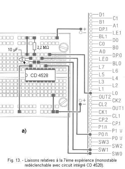
b) Insert in the matrix the integrated circuit CD 4528, of 2.2 MΩ a resistor and a capacitor of 10 µF as shown in Figure 13-a. Make the connections indicated on this same Figure.
c) Put SW0 and SW1 both at position 1.
Figure 13-b shows the circuit diagram
8. 2. - OPERATING TESTS
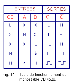
a) Connect the power supply and observe the L0 LED : if it comes on, reset the monostable by switching momentarily SW1 to position 0 and then back to position 1. The functions of inputs A, B and CD with the CD 4528 being the same as the inputs A, B and CLR of the MM 74C221, write the operating table of the monostable under consideration, following the procedure described for the MM 74C221 monostable.
Compare the data obtained with those reported in Figure 14 ; if you notice discrepancies, try again more carefully.
Now you can check the characteristic of CD 4528 that it can be retriggered.
b) Holding SW0 and SW1 in position 1, press the P0 button several times and quickly, without letting the LED L0 go out.


 Review of a Retrofit Monostable Integrated Circuit "CD 4528"
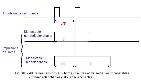
 Click here for the next lesson or in the summary provided for this purpose.
 Top of page
 Next Page