Using a Comparator Circuit and a Monostable to Realize a Combination Circuit :
9. - EIGHTH EXPERIENCE : USE OF A COMPARATOR CIRCUIT AND A MONOSTABLE TO PERFORM A COMBINATION CIRCUIT
You will now perform a circuit that is a new game : find the combination of four switches in a limited time, set in advance.
The winning combination is programmed by the one who makes the circuit. There are sixteen possible combinations.
The purpose of this manipulation is not the game itself, but the examination of an integrated circuit that you do not know yet and which is called binary comparator.
The comparator that you will use is the MM 74C85 circuit and its diagram is shown in Figure 15. This integrated circuit can compare four binary signals with four others and recognize whether they are equal or not.
In the diagram of the MM 74C85, you notice four entries labeled A0, A1, A2, A3 ; these inputs correspond to four other inputs denoted respectively B0, B1, B2, B3.
This circuit compares the eight inputs two by two, that is to say that it compares the voltage level of the input A0 with that of the input B0. Similarly, it compares the entries A1 and B1,A2 and B2, A3 and B3 together.
If the signals on the inputs are equal two by two, ie if A0 is at the same logical level as B0, as well as A1 with B1, A2 with B2, A3 with B3, the output connected to pin 3 (and which is denoted A = B) goes to level H.
In all other cases, even if only one input torque is not at the same level, the output A = B is at level L. The integrated circuit MM 74C85 has, in addition, other inputs (pins 4 , 5, 6) and outputs (pins 12 and 13) denoted by A > B, A < B, A = B.
These other inputs and outputs, however, are not considered in this experiment and their function will be developed later in the course when the binary arithmetic is processed.
9. 1. - REALIZATION OF THE CIRCUIT
a) Disconnect the power supply and remove from the matrix all the connections and components of the previous experiment.
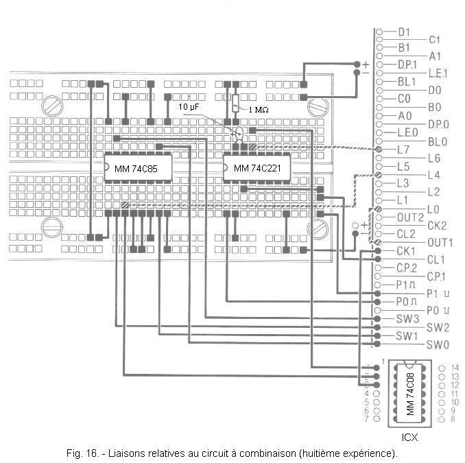
b) Insert on the matrix the integrated circuits MM 74C221 and MM 74C85, a resistance of 1 MΩ and a tantalum electrolytic capacitor of 10 µF respecting the polarities of its terminals and in conforming with Figure 16.
Then perform the links illustrated in this Figure : of the three links drawn in dotted line, make only that which connects the pin 3 of the integrated circuit MM 74C85 with the contact L4 (LED L4).
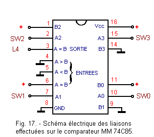
The electrical diagram of the connections made on the comparator MM 74C85 is represented in Figure 17.
The inputs A0, A1, A2, A3 are respectively connected to the switches SW0, SW1, SW2, SW3 : the inputs B0 and B2 are connected to the positive voltage, therefore they are at the level H, while the inputs B1 and B3 are connected to ground and are therefore at the level L.
Do not forget the integrated circuit MM 74C74 on the IC3 support.
c) Insert the integrated circuit MM 74C08 (which contains four AND gates) into the ICX socket.
9. 2. - OPERATING TESTS
Before completing the circuit so as to use also the monostable and an AND circuit, check first the operation of the comparator.
a) Turn all switches to the 0 position and connect the power supply.
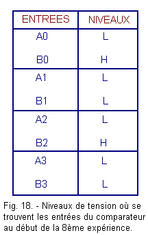
Observe LED L4 : it is off. This is because the A input are not all at the same level as the corresponding B input. Indeed, the voltage levels present on the inputs A and B being indicated in the table of Figure 18, it appears that only two out of four pairs of inputs are at the same level. Under these conditions, output A = B is at level L and LED L4 is off.
b) Put the switches in different positions, so you try the different combinations on the A inputs.
You notice that the L4 LED only comes on when the A inputs are at the same level as the corresponding B inputs and this only happens for the following combination of levels :
A0 = H
A1 = L
A2 = H
A3 = L
Naturally, it is possible to change the combination of levels on the inputs B by connecting each of them to the positive voltage or to the ground, so as to obtain the desired reference combination.
By properly positioning the switches SW0, SW1, SW2 and SW3, you will be able to turn on the LED L4.
c) Disconnect the power supply and remove the link from pin 3 of the MM 74C85 to contact L4 and connect contact L0 to contact OUT 1 of the connector group.
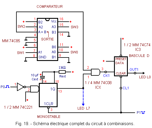
Figure 19 illustrates the circuit made. Note that the integrated circuit MM 74C74 is that permanently mounted on the IC3 support of the digilab.
Note again that the output of the binary comparator is connected to the input of the AND circuit and that the other input of this same circuit is connected to the output of the monostable.
The operation of the circuit is as follows. By pressing and releasing the push-button P1, the monostable and the rocker which controls the lighting of L0 are set to zero. Then by acting on the P0 button, the monostable generates a positive pulse having a duration of about 10 seconds, which therefore validates the output of the comparator.
If during this time (about 10 seconds) you are able to set the switches to a combination such that inputs A and B are two by two, the comparator output goes to level H and through the AND circuit, creates a front amount on the clock input of the flip-flop. The ignition of L0 is thus obtained.
To check the operation of the circuit, proceed as follows :
d) Set all switches to position 0 and connect the power supply : LED L0 will probably light up. Press the reset button P1 so that the L0 LED goes off and the circuit is in the start position.
e) Press the P0 button. You have 10 seconds to find the right combination with the switches that determines the ignition of L0.
For you who know the correct combination, it will be easy, but for another person, it will be more difficult and the difficulty can be increased by reducing the time available to find the right combination. This can be achieved by decreasing the value of Cext or Rext.
Each time L0 is lit, the circuit must be restored to the initial conditions by pressing the P1 button.
Of course, if the winning combination was not found in the allotted time, you can try again by pressing the P0 button again.
The time
available to find the right combination can be visualized by connecting the L7 LED to the output of the monostable (pin 13) as shown in dotted lines in Figure 16 and Figure 19.
In the next practice, you will examine two other circuits of great utility, the schmitt flip-flops (or Schmitt trigger) and the oscillators.


 Footer
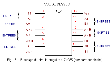
 Click here for the next lesson or in the summary provided for this purpose.
 Top of page
 Next Page