Control of Ohmmeter Transistors and Electrical Mounts :
In this practice, you will complete the assembly of the LED status indicator assembly, and after testing, you will begin the first experiments with the logic integrated circuits.
1. - PREPARATION OF MATERIALS
The materials you will use in this practice are :
8 resistors of 15 kW
1 / 4 W
tolerances ±
5% (brown - green - orange - gold)
8 transistors BC 238 B
1 braid of rigid wire isolated (length 10 cm each approximately)
1 integrated circuit MM 74C04
1 integrated circuit MM 74C08
1 integrated circuit MM 74C00
IMPORTANT NOTE:
CMOS integrated circuits are characterized by an extremely high input impedance (of the order of a million megohm) and an accumulation of electrostatic charges on their terminals can easily give rise to a difference of electrical potential sufficient to cause, under certain conditions, a destructive electric shock.
To prevent this from occurring, appropriate devices should be used, either when storing these components or when using them.
Many no conductive materials, especially those made of plastic, can, by prolonged friction, be the object of an accumulation of static electricity.
For this reason, in packaging and during transport, the CMOS integrated circuits are protected by boxes or blocks of conductive spongy substance. By keeping the lugs of the integrated circuits short-circuited, it avoids any potential difference between them. A human being can also be charged with static electricity, usually by rubbing, especially if he is wearing woolen or synthetic fiber garments, or if he is wearing rubber soled shoes, walking on the carpet, or it is in contact with seats covered with plastic material. To avoid damage to CMOS integrated circuits that you have purchased from electronic stores, you must observe the following precautions :
- remove the integrated circuits from the graphitized foam which serves as a support for them before their immediate use,
- before taking an integrated circuit with your hands, it is good to discharge the possible static electricity of your own body by touching a grounded metal mass, for example drinking water piping or central heating,
- as far as possible, avoid contacting fingers with several pins of an integrated circuit,
- before inserting an integrated circuit into a socket, always make sure that the power supply is not connected,
- after use, always replace the integrated circuit on its graphitized foam, which will keep it in good condition.
As for the transistors, it is good to check their condition before using them ; let's see how they can be controlled using the ohmmeter.
To completely check the proper functioning of a transistor, the safest system is to use a transistormeter. However, in the absence of such an apparatus, it is still possible to check the good state of a transistor by making resistance measurements between its three emitter, base and collector terminals by means of an ohmmeter.
In Figure 1-a, we can see how to identify the three terminals of the NPN type transistor that you bought, (you also have the option to purchase the documentation, "Global Directory of Transistors"), while Figure 1 -b represents the corresponding graphic symbol.
To carry out the check of this component, proceed according to the following instructions taking into account that, as seen during the LED test, the controller to be used must be of the traditional type. An electronic or digital type controller does not have the appropriate characteristics to perform this type of control.
Place the controller on the Ω X 1 000 gauge and place the "+" touch pad of the ohmmeter (usually corresponding to the black socket) in contact with the terminal of the base, and the "-" to the red socket) first in contact with the terminal of the transmitter and then with that of the collector as shown in Figure 2-a. The needle of the device must indicate in both cases a low resistance value (direct resistance) of between a few kΩ and 15 kΩ.
Now reverse the polarities of the ohmmeter, as shown below in Figure 2-b, by placing the "-" point, that is, the red on the base terminal, and the other point first touching. with the transmitter terminal and then with the collector terminal ; the galvanometer needle must in both cases indicate an infinite resistance (inverse resistance).
Finally, check the insulation between the emitter and the collector by putting the ohmmeter's contact points in contact with its two terminals, first in one direction, then in the other ; in both cases the measurements will have to provide a fairly high resistance value, practically infinite.
The method you have put into practice can naturally be used to control PNP transistors. It suffices to remember that in this case the direct and inverse resistance values measured between the base and the transmitter and between the base and the collector, are obtained by placing the test probes of the ohmmeter in the opposite direction of that indicated for the NPN transistor.
It is obvious that knowing the polarities of the ohmmeter and the indicated method, it is possible to determine if a transistor is NPN type or PNP type. Indeed, if one finds a low value of resistance (direct resistance base-emitter, base-collector) by placing on the base the tip of key "+" (black), it is about a transistor of the type NPN. If the same direct resistance is obtained by placing the "-" (red) touch point on the base, the transistor is of the PNP type.
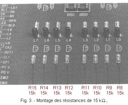
a) - Take the resistance R8 of 15 kΩ 1 / 4 W, tolerance ± 5% (brown - green - orange - gold) and after having properly folded the legs, place it on the circuit board at the location marked by the corresponding acronym. Make sure they are in contact with the circuit. Perform the leg welds as you have done for the other resistors.
b) - In the same way, weld the appropriate resistors R9, R10, R11, R12, R13, R14 and R15 (Figure 3) all 15 kΩ 1 / 4 W tolerance ± 5% (brown - green - orange - gold).
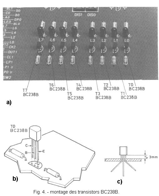
c) - Arrange transistor T0, type BC 238 B or its equivalent, in the position indicated by the screenprint (Figure 4-b). Make sure to identify his three legs. Place this component so that it is raised about 3 mm from the circuit as shown in the picture Figure 4-c, then spread slightly the terminals of the emitter and the collector so that by turning over the circuit, the transistor keeps the good position ; finally solder the three legs and then cut the excess length.
d) - Perform the assembly and soldering of transistors T1, T2, T3, T4, T5, T6 and T7 (Figure 4-a) according to the instructions provided for mounting the first transistor T0.


 Control of transistors at the ohmmeter
 Click here for the next lesson or in the summary provided for this purpose.
 Top of page
 Next Page