Above all, make an off-line test of the circuit by placing the ohmmeter on the Ω x 1000 gauge and checking that between the L0 contact of all the connectors and the electrode of the base (see the middle one) of transistor T0, you have to find a resistance value between 14 kΩ and 16 kΩ. This control is clearly shown in the picture (Figure 5).
Then continue the unpowered control by taking the measurements between the different points indicated in the table of Figure 6. If one of these measurements reveals an infinite resistance, this indicates a break between the two measuring points ; in this case it is necessary to look at the state of the resistance concerned by the measurement, to check the continuity of the copper tracks and then to redo the measurements.
Fig. 6. - Table for the off-voltage control of all weld points made.
N°
POINTS OF CONTACT WITH THE OHMMETER
VALUE TO OBTAIN
1
Between contact L0 and the base of T0
14
at 16 kW
2
Between contact L1 and the base of T1
14
at 16 kW
3
Between contact L2 and the base of T2
14
at 16 kW
4
Between contact L3 and the base of T3
14
at 16 kW
5
Between contact L4 and the base of T4
14
at 16 kW
6
Between contact L5 and the base of T5
14
at 16 kW
7
Between contact L6 and the base of T6
14
at 16 kW
8
Between contact L7 and the base of T7
14
at 16 kW
9
Between the contact (-) and the transmitter T0
0
W
10
Between the contact (-) and the transmitter T1
0
W
11
Between the contact (-) and the transmitter T2
0
W
12
Between the contact (-) and the transmitter T3
0
W
13
Between the contact (-) and the transmitter T4
0
W
14
Between the contact (-) and the transmitter T5
0
W
15
Between the contact (-) and the transmitter T6
0
W
16
Between the contact (-) and the transmitter T7
0
W
3. 2. - CONTROL ON TENSION AND TESTS
You will now perform a function check of all LEDs.
For this, it is necessary above all to prepare a wire to be inserted into the contacts of the group of connectors in order to supply the control current to the witnesses.
Proceed as follows :
a) - Cut into the insulated tinned wire braid you purchased (approx. 0.50 mm2 section), a piece about 5 cm long and strip the ends 3 to 4 mm. To carry out this operation by avoiding scratching or bending the inner conductor, it is advisable to use the soldering iron ; cut the insulating jacket at the chosen location by pressing the tip of the hot iron tip all the way around the conductor. Then remove the sheath by pulling with your fingers.
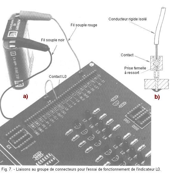
b) - Using the insulated rigid wire you have prepared, connect the L0 contact of the connector series to the nearest "+" contact, without soldering, as shown in the picture (Figure 7-a).
To perform this operation, simply insert the ends of the wire into the holes of the two contacts by exerting a slight pressure, so that the wire penetrates well into the hole of each contact and is held by the internal springs (Figure 7-b).
IMPORTANT NOTE :Always be careful to make sure each time you make connections to the connector group, that the ends of the wire to be used are not damaged by small creases or scratches to avoid damaging the contacts or run the risk of seeing the end of the wire break inside a contact, which would make it necessary to replace the corresponding connector.
c) - Power the circuit by putting the crocodile clip of the red power cord on the "+" of the 4.5 V battery and the black cord clamp on the "-" tab of the same battery ; you notice that the LED L0 lights up.
d) - Remove the lead wire from the "+" contact of the connector group and insert it into the "-" contact ; you notice that the LED L0 goes out.
With this test you checked the operation of the L0 indicator. Thread the conductor back into the "+" contact so that the LED stays on.
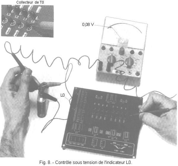
Place the controller on DC 1 V voltages and perform the first control shown. It concerns the measurement N° 1 of the table of Figure 9.
Then continue the check under tension, making the following measurements between the points shown in Figure 9, remembering that the ground corresponds to the "-" terminal of the battery.
WARNING
:
The circuit ground corresponds to the "-" of the power supply
The measured voltage values are normal if they lie between the two extreme reference values indicated.
If the LED does not come on and the measurement results are not the same, first make sure that the LED has been wired correctly, then consult the table in Figure 10. You can draw some indications from it useful for locating the defect.
Fig. 10. -
Troubleshooting information for possible faults during live control.
ANOMALY ENCOUNTERED
PROBABLE CAUSES
You find 0 V on the collector of T0
Resistance R0 is cut
LED is defective
You find + 3 V on the collector of T0
LED is connected upside down
Transistor T0 is defective or plugged backwards
The resistance R8 is cut
Vous
You find + 0.08 V on the anode of the L0 diode
LED L0 is short-circuited
Vous
You find + 4.5 V on the basis of T0
Transistor T0 is faulty or badly wired
You find 0 V on the basis of T0
The resistance R8 is cut
Transistor T0 is defective
You find 0 V on the contact L0
The connection between contacts L0 and "+"
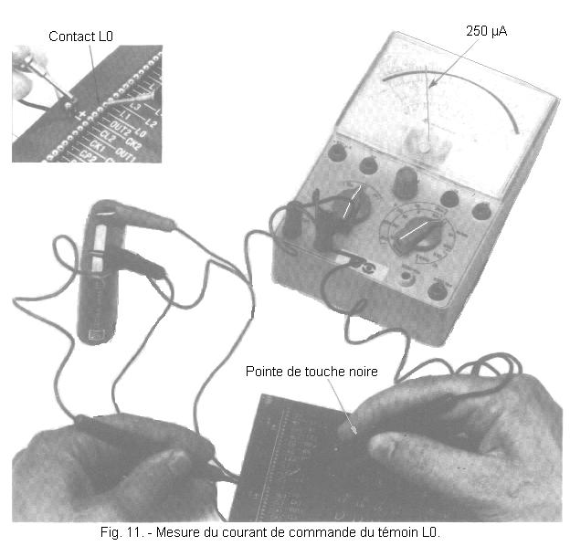
These checks having proved satisfactory, you can switch to measuring the control current of the transistor T0.
e) - Remove the connection between the "+" contact and the L0 contact ; place the controller on DC 1 mA. Touch the contact L0 with the black contact tip and the "+" contact with the red tip as shown in Figure 11. The LED comes on again and the hand indicates a current between 0.2 and 0.3 mA, that is to say 200 and 300 µA (microamperes).
f) - After checking the L0 indicator, replace one end of the insulated rigid conductor in the "+" contact and with the other end touch contacts L1, L2, L3, L4, L5, L6 and L7 ; the corresponding LEDs light up in sequence, one after the other.
If one of the LEDs does not light up, check the voltages at the different points of the corresponding transistor circuit and locate the fault following the instructions given previously for the L0 indicator.
Having finished testing all the indicators, unplug the power supply by removing the red and black alligator clips from the battery.
3. 3. -CIRCUIT
EXAMINATION OF THE INDICATOR ASSEMBLY
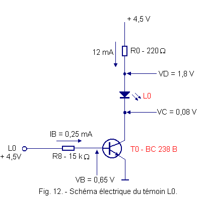
The indicator assembly is composed of eight identical and independent circuits ; therefore examine only one of them, for example the L0 indicator circuit whose electrical diagram is shown in Figure 12, it being understood that the following considerations are also valid for each of the other indicators.
In practice, the transistor T0 behaves as a switch controlled by the signal applied to the input, that is to say on the base.
More specifically, when a high voltage level is applied to the input L0 (in this case between + 4.3 + 4.5 V,measurement N° 3 of the table of Figure 9), the base of the transistor
T0 is traversed by a control current (IB = 0,25
mA,control of Figure 11) which carries it to saturation.
The voltage of the collector VC then decreases until it reaches approximately one tenth of a volt, for example at + 0.08 V (value between + 0.06 and 0.1 V,measurement N° 1 of the table of Figure 9) and the LED lights up, as you have seen experimentally.
Under these conditions, the current flowing in the LED is limited by the resistance R0.
Assuming that the voltage measured on the anode of the LED is +
1,8 V (value between
1,6 V
and 2 V, measurement N° 2 of the table of Figure 9), there will be at its terminals a voltage of 1,8
V - 0,08 V = 1,72 V which is a typical value for the majority of LEDs.
If on the other hand on the input L0, there is a voltage lower than 0.7 V (in our case 0 V, when L0 is connected to the terminal "-"), the base of the transistor is no more polarized, and it remains stuck, that is to say it behaves like an open switch. The LED remains off.
To turn on an LED, it is necessary to have a current of 10 to 15 mA that a digital type integrated circuit is not always able to provide.
That is why we use to control the LED diode to a transistor that consumes only 0.25 mA on the base, but can provide 12 mA on its collector. This transistor is called DRIVER, English term meaning driver. Some power integrated circuits can fulfill the same role, they are called "BUFFER current" (buffer meaning tank in English).
The light indicator thus produced makes it possible to distinguish a high voltage level (LED on) from a low level (LED off) at the output or at the input of a digital circuit. It requires only a control current of 0.25 mA only.


 Examination of the circuits of the indicator set
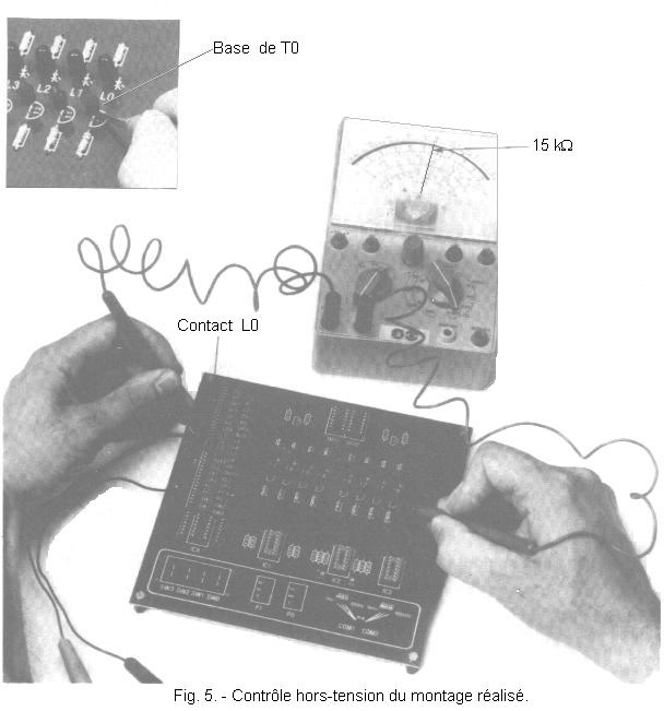
 Click here for the next lesson or in the summary provided for this purpose.
 Top of page
 Next Page