You will now perform a series of checks allowing you to check the accuracy of the editing done so far. You will be able to proceed safely to the exercises that will follow.
3.1. - OFF-VOLTAGE CONTROL
Place your controller in an ohmmeter on the W
x 1 000 gauge.
Put the contact tips in contact with the two alligator clips at the ends of the red and black power supply wires.
The device must indicate an infinite value.
If the measured resistance value is zero (full scale needle), this indicates the presence of a short circuit.
In this case, you will have to re-check carefully all the welds made, to locate the place of the undesirable contact, then eliminate the short circuit using if necessary the soldering iron and the braid to be desoldered :
by keeping one of the contact points in contact with the alligator clip of the red flexible wire, touch with the other point one then the other of the two contacts marked by the sign (+) as illustrated in figure 20.
In both cases, the controller must indicate a null resistance : if the resistance turns out to be infinite (the needle remains on the left), check the soldering of the pins of the two connectors and that of the red flexible wire on the copper band (+ B).
connect one of the two tips to the crocodile clip of the black flexible wire and put the other in contact with each of the two contacts marked with the - sign.
In both cases, the measured value must be zero. If this is not the case, check the solderings of the pins of the two connectors and the black flexible wire on the copper - B strip.
first, make sure there is no metal under the printed circuit, as this may cause an accidental short circuit.
If the battery blades are not accessible, remove the paper warranty tape.
connect the black wire clamp to the (-) battery blade (the longest) and the red wire clamp to the (+) blade.
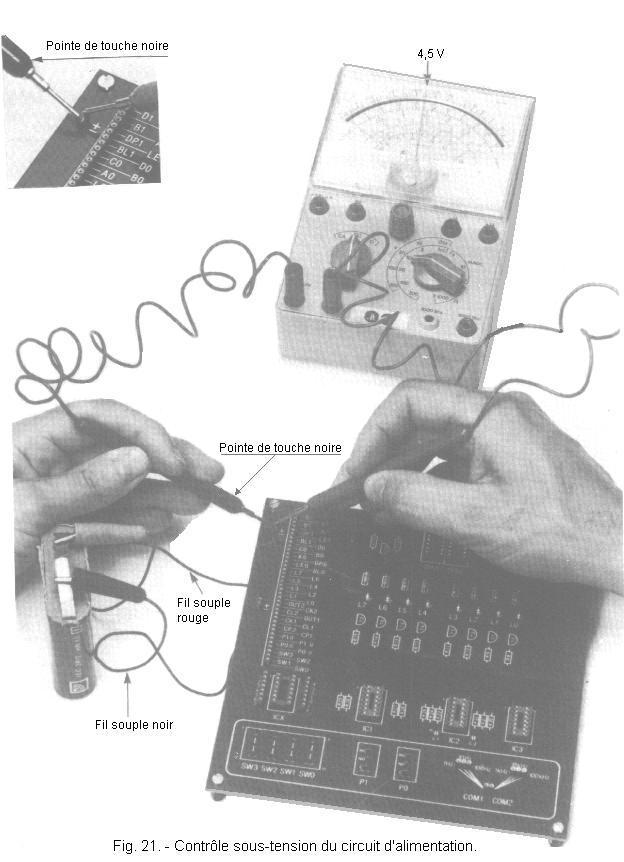
Prepare the controller for VCC measurement (DC voltages), 10 gauge and, respecting the polarities of the controller, put the contact tips in contact with the two pins "+" and "-" as clearly illustrated in Figure 21.
The device must indicate a voltage between 4.4 V and 4.8 V.
You should also find the same voltage on the other two "+" and "-" contacts.
If the measured voltage is lower (see zero) at both measuring points, disconnect the battery and check the voltage between the two blades "+" and "-". It must be between 4.4 V and 4.8 V.
After this check, if the battery delivers the normal voltage we will direct the searches towards the presence of a cold junction that will be redone on the pins "+" and "-" of one or the other connector.
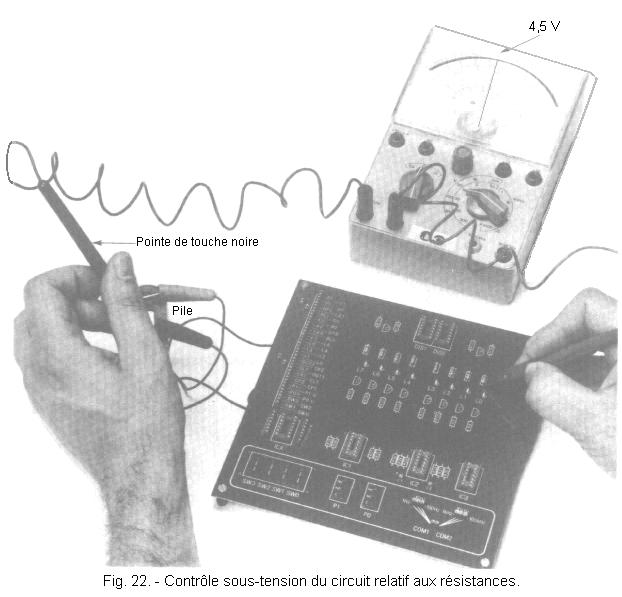
keeping the tip of the controller in contact with the clamp of the black flexible wire, test with the tip of the positive pole, one after the other, the lower terminals (by looking at the printed circuit at the place) eight resistors of 220 Ω as shown in Figure 22.
On each of the eight resistors, you must find the battery voltage.
Otherwise, the ohmmeter should be checked for the value of the resistor on which the voltage is not correct, as well as the welds at its terminals.
Lastly, also check the continuity of the track connecting the resistance in question to the copper + B band of the power supply using the ohmmeter.
In general, to verify with certainty the continuity of the tracks of a printed circuit and to ensure that no undesirable contact remains between the tracks or pellets, it is sufficient to observe by transparency the printed circuit on the side of the tracks in question. lighting the other side with a lamp which is not possible in some cases, the screen printing has made the card opaque. However, we advise you to observe the circuit board for lack of better.
You will now set up the LEDs and make some measurements on these diodes.
The LEDs are light-emitting diodes when they are forward-biased or forward-biased (the anode must be positive with respect to the cathode). A complete and detailed review of the diode will be in a lesson titled Technology 1.
On the simulator, the LEDs are used as logical level indicators. Controlled by an adaptation circuit, they make it possible to distinguish one of the two binary states (high level : presence of voltage, illuminated LED corresponding to binary state 1, low level : absence of voltage, LED off = binary state 0).
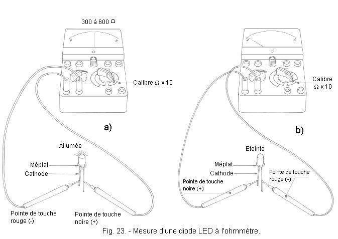
Before mounting the LEDs, it is good to check them : to do this, simply put the controller in the ohmmeter position (Ω x 10 gauge). Place the positive tip of the ohmmeter on the anode, the other on the cathode : the LED must then light (Figure 23-a), the galvanometer needle must indicate a resistance value between 300 and 600 Ω.
It should be remembered that on a current type controller, in the ohmmeter position, the positive polarity of the battery used for this measurement appears on the terminal called "common".
By inverting the polarities across the LED, you notice that it does not turn on and the controller indicates infinite resistance (Figure 23-b).
It is not possible to perform this test with a digital controller because the current flowing through the ohmmeter circuit would not be sufficient to turn on the LED.
After verifying the correct operation of the eight LEDs, you can install them :
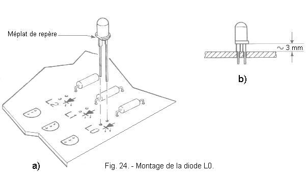
take a LED and insert it in the place provided on the printed circuit board and marked by the symbol L0 referring to Figure 24-a for a correct connection of its two terminals.
If the diodes you have in your possession have a stop shoulder on their connections, they will automatically be positioned at the correct distance of about 3 mm from the PCB, as shown in Figure 24-b. It is therefore sufficient to hold them in place with one finger, then turn the circuit over and solder the two terminals to the corresponding copper pads.
However, some LEDs may have no shoulder on their connections.
In this case, hold them at 3 mm above the circuit, then, on the copper side, move their connections slightly apart. Thus, you can return the circuit, the diode remains in place while performing its welding.
After this operation, you can cut off the excess portion of the LED connections.
Before proceeding to the assembly of the following ones, carry out the control of the first one :
power the circuit by connecting the alligator clip of the red cord to the "+" terminal of the battery and the clamp of the black cord to the "-" terminal.
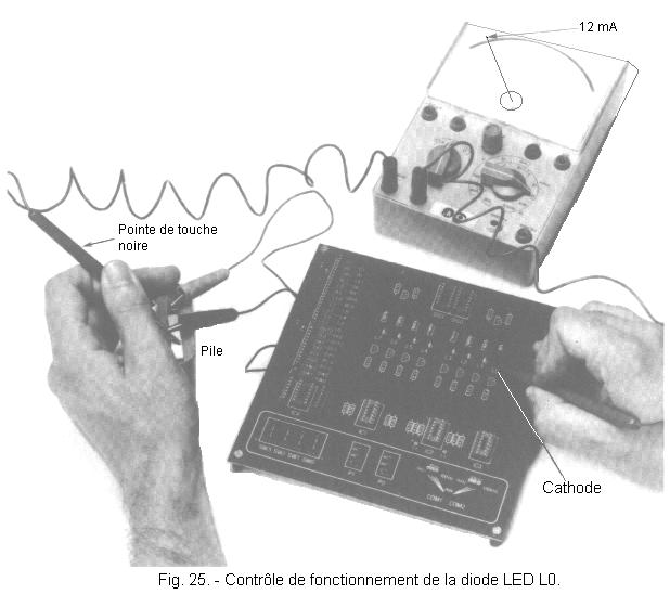
set the controller for the DC current measurement to a rating greater than 25 mA at the end of the scale, place the black test tip on the "-" terminal of the battery and the red test probe in contact with the cathode of the battery. LED, as shown in Figure 25. This contact is established, the LED is illuminated and the galvanometer must indicate a current between 10 and 15 mA.
If the LED does not light and the controller does not report any current flow, you must first ensure that you have correctly identified the anode and cathode terminals of the LED. If you have wired it upside down, it is necessary to unsolder it with the appropriate braid and replace it correctly, paying more attention to the indications and figures quoted.
If, on the other hand, the LED still does not light and the controller indicates a current between 19 and 25 mA, it is likely that the red test tip was mistakenly in contact with the anode instead of the cathode.
Finally, despite all these checks, if you do not get the illumination of the LED, make sure again the presence of a voltage on the lower limit of the resistance equal to that of the battery (see check under voltage, paragraph 3.2). This voltage being verified, it can be assumed that the diode has failed.
Desolder it and check it with the ohmmeter and eventually replace it with another one.
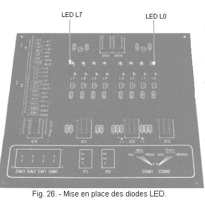
The functional control of the diode in place being conclusive, you can proceed to the assembly of the seven other LEDs (Figure 26) :
following the instructions previously provided, solder the remaining seven LEDs to the locations on the printed circuit board marked L1, L2, L3, L4, L5, L6 and L7 with all due attention to the identification of the cathodes. Finally, check the operation of each of them as well as the current absorbed in the same way as for LED L0.
With the control of all LEDs, ends the first practical realization.
In the next, you will continue mounting the simulator by realizing the transistor control circuit of each of the LEDs and you will perform the first tests with logic integrated circuits.
At the beginning of this lesson, the relationship between theory and practice is not obvious. However, as the progression progresses, the subjects will juxtapose each other and link chapters into chapters. Your exam will have to progress in the same order.
You will also find information and technical notices on components, integrated circuits, etc. ...
To finish this lesson, chapter 5 summarizes the main component marking systems.
The identification of the value of the resistors and the capacitors can be done in several ways according to the manufacturers :
1 - Resistance marked "in clear".
Sometimes this value appears clearly, as well as tolerance, without resorting to any particular code ; but this is very rare.
Often, the symbol Ω is omitted and there are only K or M prefixes for large values, either next to or below the number. For example : 1 K - 270 - 1M08 - 9k00 means 1 kΩ - 270 Ω - 1.08MΩ and 9 kΩ.
Frequently, the symbol Ω is replaced by the letter R for values less than 1 kΩ. If it is placed before the number, it indicates a comma preceded by a zero. For example, the following indications : 4 R 5 - 10 R 0 - 900 R - R 30 indicate respective values of 4.5 Ω - 10 Ω - 900 Ω and 0.3 Ω.
2 - Resistance marked by the 4 colors code and remember that we already talked about it in the lessons of fundamental electronics and we report it here (Figure 11). It is the most used. The table below reminds you.
3 - Resistance marked by the 5 colors code and we report the same table already explained in the lessons of fundamental electronics (Figure 12).
This is the same principle as for the previous code. See the table below. Here is an example of reading with this code :
White
(9) Black
(0)
Black (0)
Yellow (x 10 000)
Brown (1%) = 9 MW
1%
Orange
(3)
White (9)
Red (2)
Gold
(x 0,1)
Red (2%) = 390
W 2%
Yellow
(4) White
(9) White
(9) Black
(x 1)
Gold (5%) = 499
W 5%
4 - Capacitor marked "in clear".
The value of the capacitance, the working voltage and the tolerance are expressed clearly on the capacitor body. But many builders remove from measure the units of measure and zeros that precede the comma.
If the number that expresses the capacity begins with a number other than zero, the unit is the picofarad. If this number is followed by the lowercase letter "n" or "k", it is nanofarad.
If the number indicating the capacity begins with a zero, a comma or a point, the unit is the microfarad. The dot preceding the first digit indicates an imaginary comma preceded by a zero.
Example:
1000 10 %
630 = 1000 pF 10 % 630 V
1 n 0 = 1 nF
470 k = 470 pF
10 %
.01 = 0,01 µF = 10 nF
100 M = 100 pF 20 %
The first capital letter following the number indicates the tolerance and the second, if it exists, is the temperature coefficient. The most common tolerances for ceramic capacitors are 2.5% (H), 5% (J), 10% (K), 15% (L), and 20% (M).
For polystyrene capacitors, a colored band can also be found indicating the voltage according to the following correspondence : Blue = 25 V - Yellow = 63 V - Red = 160 V - Black = 630 V.
WARNING :
In some cases, the number indicating the value of the capacity is written in code. It is always an integer of three digits, the last (right) is different from zero. The first two digits are the first two significant digits and the third digits indicate the number of zeros to add to obtain the value of the capacity (in picofarad).
Example:
472 = 47 00 = 4 700 pF = 4,7 nF
101 = 10 0 = 100 pF = 0,1 nF
5 - Capacitor marked with the color code (Figure 23).
This code is similar to the one used for resistors. The table below allows you to read them which we had already explained in the lessons of fundamental electronics.
6 - Locating the electrodes of an active element.
The identification of the transistors can be done in different ways : a point of color, a metal pin, a flat, etc. ...
Integrated circuits are also marked by a recess on the housing.
For components used in practical assemblies, pinning will always be given.


 Installation and functional control of LED diodes
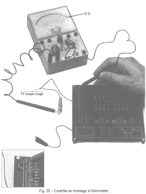
 Click here for the next lesson or in the summary provided for this purpose.
 Top of page
 Next Page