3. - SECOND EXPERIENCE : EXAMINING A 4 BITS DIGITAL / ANALOG CONVERTER
By using two operational amplifiers and a resistor network, you will realize a 4 bits D / A converter.
The operating principle is based on the possibility of varying the gain of an amplifier circuit by modifying the value of the resistance connected to the inverting input of an operational amplifier.
It is a weighted resistance converter.
3. 1. - REALIZATION OF THE CIRCUIT
The electrical diagram of the assembly to be carried out is given in Figure 5-a.
a) Remove from the matrix all the links and components related to the first experiment.
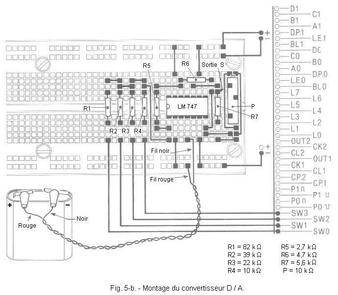
b) Make the assembly located in Figure 5-b, without connecting for the moment the negative pole of the battery.
c) Set the switches SW0, SW1, SW2 and SW3 to the 0 position.
3. 2. - OPERATING TEST
a) Connect the negative pole of the battery to the circuit using the black crocodile clip, then turn on the digilab.
b) Prepare the controller for the C.C. voltage measurement on the 10 volts rating.
Measure the output voltage S of the circuit. To do this, connect the negative tip to ground and the positive tip to the R7 terminal connected to pin 10 of the LM 747. You must find zero or very low voltage (offset voltage).
c) Turn all switches to position 1.
d) Adjust the trimmer P so that the output voltage S is equal to 3.75 volts. You have calibrated the converter.
e) Put the inverters SW1, SW2 and SW3 on 0 and leave SW0 on position 1.
f) Measure the output voltage S. It is about + 0.25 volts. This value corresponds to the least significant bit (LSB) of the binary number present at the input of the converter.
g) Put SW0 on 0 and SW1 on 1.
h) Measure the output voltage.
You must find about + 0.5 volts. The weight of this bit (bit 3) is twice that of the LSB.
i) Set SW1 to 0 and set SW2 to position 1.
j) Measure the output voltage of the D / A converter.
You find about + 1 volt, this value corresponds to bit 2.
k) Set SW2 to 0 and SW3 to 1 and perform the same measurement as before.
You must find about + 2 volts, this value corresponds to the MSB (bit 1). This series of measurements allowed you to check the weight of each bit.
It is very likely that you have not quite found the values shown for two reasons.
First, the values of the resistors R4, R3, R2 and R1 should follow a geometric progression of reason 2, that is to say, be worth 10 kΩ, 20 kΩ, 40 kΩ and 80 kΩ. However, the closest standardized values of the E12 series are 10 kΩ, 22 kΩ, 39 kΩ and 82 kΩ.
Then there is the resistance tolerance and the controller accuracy that come into play in the actual value found.
Nevertheless, this experience has value only by its didactic side.
l) Now realize all possible combinations using the switches and for each of them, measure the output voltage.
Now realize all possible combinations using the switches and for each of them, measure the output voltage.
The second column shows you the theoretical values of the output voltage.
m) Record these theoretical values on the graph in Figure 7 which shows the ideal transfer characteristic of this 4 bits D / A converter.
By way of example, the graph of Figure 8 represents the real characteristic of a 4 bits D / A converter.
You notice that this characteristic is not linear and that the converter has a nonzero offset voltage (0.34 volt for 0000 input).
n) Turn off the digilab and unplug the battery.
The digital / analog converter that you have just experimented with is one of the simplest we can achieve. It has a low resolution and moreover, its accuracy is not very high.
On the market, there are D / A converters made in integrated circuits.
We will examine the operation of this converter.
The Figure 9 shows how the binary number is applied to the input of the converter using the 4 switches.
When a bit is 0, the corresponding resistor is grounded by the switch. When it is 1, the resistance is connected to + 5 volts thanks to this same switch.
Consider the circuit of Figure 9.
The resistance R4 corresponding to the MSB is connected to + 5 volts and the other resistors (R3, R2 and R1) are connected to ground.
The inverting input (-) of amplifier A is at potential 0 since the non-inverting input (+) is wired to ground. Therefore, in the calculation of the gain of A, the three resistors R1, R2 and R3 do not intervene.
This G1 gain is :
G1 = - (R5 / R4) = - (2,7 kW
/ 10 kW) = - 0,27
The output signal on pin 12 is in phase opposition with respect to the input signal on pin 1.
The voltage VA on pin 12 is :
VA = G1 x VI = - 0,27 x 5 = 1,35 volt
This first stage A operates the actual conversion D / A. Nevertheless, it is desired to obtain a positive voltage so this first stage A is followed by a second stage B voltage amplifier and inverter.
The output voltage VB must be + 2 volts. The gain G2 of the amplifier B is therefore :
To obtain the necessary gain (-
1,48148), simply adjust the trimmer P.
The total gain G
of the converter is therefore :
G = G1 x G2
= (- 0,27) x (- 1,48148) @
0,4
Now, G
is equal VB / Ve, hence :
For Ve = 5
volts, G2 = 1,48148, R5 = 2,7 kW
we obtain :
It suffices to apply this formula (3) to calculate the voltage VB as a function of the binary number applied to the input.
For bit 1
(MSB), we will have VB = 20 / R4 = 20 / 10 = 2 volts
For bit 2, we will have
VB = 20 / R3 = 20 / 22 = 0,9 volt
For bit 3, we have
VB = 20 / R2 = 20 / 39 = 0,5 volt
For bit 4
(LSB), we have
VB = 20 / R1 = 20 / 82 = 0,24 volt
For any binary number, two methods can be used :
Either we calculate the equivalent input resistance, equal to the resistances connected in parallel and connected to the + 5 volts. Then just apply formula (3).
Either we add the output voltages corresponding to each bit to 1.
For example, for 11002,
the bits 1 and 2
are at 1. Thus
+ 2 volts and + 0,9 volt are added and the result is :VB = + 2,9
volts.


 Footer
 Click here for the next lesson or in the summary provided for this purpose.
 Top of page
 Next Page