Study of the LM 555 to Realize an Astable Multivibrator :
4. - FIRST EXPERIENCE : EMPLOYMENT OF THE LM 555 AS MONOSTABLE
Associated with a network RC, the circuit LM 555 makes it possible to realize a monostable whose duration of the pulse will be according to the constant of time RC.
4. 1. - REALIZATION OF THE CIRCUIT
a) Insert on the matrix the integrated circuit LM 555, the capacitor C1 of 0,01 µF, the tantalum electrolytic capacitor C2 of 1 µF and the resistance R1 of 1 MΩ as illustrated Figure 8-a.
b) Make the connections indicated in this same figure.
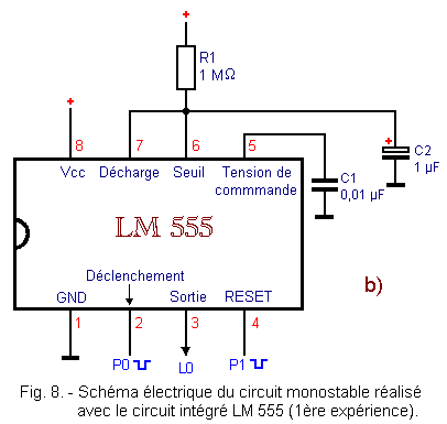
The electrical diagram of the assembly is given in Figure 8-b.
4. 2. - OPERATING TEST
a) Turn on the Digilab.
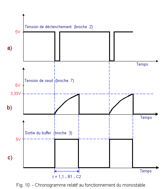
b) Press and immediately release P0. You notice that the L0 LED lights up for about 1 second.
c) If you press P1 before the L0 LED is off, you notice that it goes off immediately. Indeed, the RESET input connected to the P1
contact is activated.
d) Turn off the Digilab.
e) Replace the 1 µF - 12V electrolytic capacitor with a 10 µF - 12V electrolytic capacitor.
f) Switch on the Digilab again.
g)Press P0. You notice that the L0 LED lights up for 10 seconds, ten times longer than the previous test.
h) The test is finished, you can turn off the Digilab.
To analyze the operation of this monostable, refer to Figure 9.
In the initial conditions of rest, the
output of the flip-flop is at the level H and the transistor T1 leads. Capacitor C2 is thus short-circuited and the voltage at its terminals is close to zero.
The output of the buffer (pin 3) is at level L.
The input (pin 2) of the integrated circuit (inverting input of the tripping comparator) is at the level H, therefore the output of this comparator is at the level L since the non-inverting input is at the potential 1 / 3 of Vcc, approximately 1.67 volts.
When P0 is pressed, the inverting input of this comparator goes to the level L, thus to a voltage level lower than that of the non-inverting input. The output of the comparator goes to level H. The
output of the flip-flop thus goes to the L level and the output of the buffer at the level H, as indicated in Figure 10-a.
The transistor T1 is blocked and the capacitor C2 is charged through the resistor R1.
The Figure 10-b shows the variation of the voltage across C2.
This voltage is applied to the non-inverting input of the threshold comparator. The voltage on the inverting input of this comparator has a value of : (2 / 3) x 5 = 3.33 volts.
When the potential on pin 6 exceeds this voltage of 3.33 volts, the comparator output goes to level H.
The
output of the rocker RS therefore returns to the level H, while the transistor T1 saturates and allows the capacitor C2 to discharge very quickly.
The cycle of the monostable is thus finished.
The duration of the output pulse is directly proportional to the product R1 x C2. It is equal to 1.1 x (R1 x C2).
In this case, we have :
T = 1,1 x (R1 x C2)
= 1,1 x (106 x 10-6) = 1,1 second
By pressing the P1 button, the RESET input is activated and resets the RS flip-flop, which interrupts the charging of the capacitor if the latter was in the charging phase.
If this reset input is not used, it is good to wire it to the voltage Vcc, to prevent noise from changing the duration of the output pulse.
The capacitor C1, connected to the inverting input of the threshold comparator, serves to eliminate any interference that may interfere with the operation of the circuit (decoupling capacitor).
5. - SECOND EXPERIENCE : USE
OF THE INTEGRATED CIRCUIT LM 555 TO CARRY OUT AN ASTABLE MULTIVIBRATOR
With a limited number of components and external links, the LM 555 integrated circuit can function as an astable multivibrator.
5. 1. - REALIZATION OF THE CIRCUIT
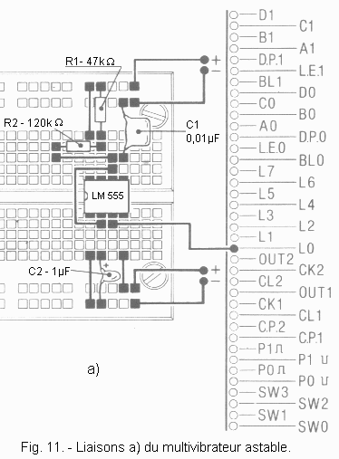
a) Remove from the matrix the connections and components related to the previous experiment, leaving the LM 555 in place.
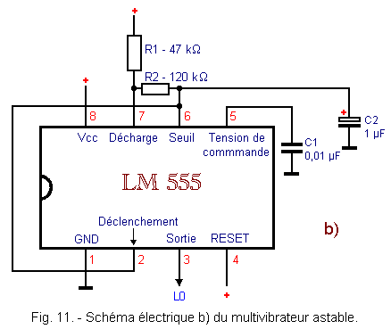
b) Insert on the matrix the two capacitors C1 of 0.01 µF and C2 of 1 µF and the two resistors R1 of 47 kΩ and R2 of 120 kΩ in the position indicated Figure 11-a.
c) Make the connections shown in this Figure 11-a.
The electrical diagram is given in Figure 11-b.
5. 2. - OPERATING TEST
a) Turn on the Digilab. You observe that the LED L0 flashes at a frequency of 5 Hz.
b) Turn off the Digilab.
As you have seen, the circuit oscillates freely and generates a rectangular signal. In order to analyze the operation of this assembly, observe the wiring diagram of the circuit in Figure 12.
We know that the output
is at level L at power up. The transistor is off and the capacitor C2 is charging through R2 and R1.
When the voltage across C2 reaches 2 / 3 Vcc, the output of the threshold comparator goes to H and
goes to H.
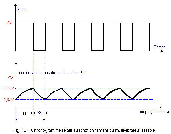
The timing diagram of Figure 13 represents the evolution of the voltages at the terminals of C2 and at the output of the oscillator.
The transistor saturates, allowing the discharge of C2 through R2 during the time t2. You can note that in the case of the monostable, the capacitor discharge was almost immediate since there was no resistance.
Moreover, in the oscillator circuit, the trip input is connected to the threshold input, so when the voltage across C2 drops below 1 / 3 Vcc, the trigger comparator switches and the output
return to level L.
The transistor locks again and the capacitor C2 can recharge. A new cycle begins again. As shown in Figure 13, the voltage across C2 varies alternately between 2 / 3 Vcc and 1 / 3 Vcc.
Capacitor C2 charges for the time : t1 = 0,693 x (R1 + R2) x
C2.
It is discharged during the time :
t2 = 0,693 x R2 x C2.
The period T of the rectangular signal is : T = t1 + t2 = 0,693 x
(R1 + 2R2) x C2
With the experimental values we obtain :
t1 = 0,693 x (47 x 103 + 120 x 103)
x 10-6 = 0,12 second
t2 = 0,693 x (120 x 103
x 10-6) = 0,08 second
T = 0,12 + 0,08 = 0,2 second
The frequency is :
F = 1 / T = 1 / 0,2 = 5 Hz.
6. - THIRD EXPERIMENT : RECTANGULAR
SIGNAL GENERATOR WITH VARIABLE FREQUENCY
While retaining the previous editing, you will in this experiment realize an astable multivibrator whose oscillation frequency can vary using a potentiometer.
6. 1. - REALIZATION OF THE CIRCUIT
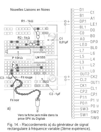
a) Remove from the mounting only the resistors R1 and R2, the connection with the LED L0 and that between the pin 3 of the LM 555 and one end of the resistor R2 of 120 kΩ. (See Figure 14-a).
b) Complete the circuit by inserting on the matrix the potentiometer of 10 kΩ, the two new resistors R1 and R2 of 1 kΩ, the tantalum electrolytic capacitor C3 of 10 µF and the cord of the loudspeaker, as well as the new connections indicated Figure 14-a.
c) Insert the male jack plug into the SPK socket of the Digilab.
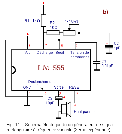
The electrical diagram of the realized circuit is given in Figure 14-b.
You notice that the speaker is connected to the output of the astable multivibrator. The rectangular electrical signal is therefore translated into an acoustic signal by the loudspeaker.
6. 2. - OPERATING TEST
a) Turn on the Digilab. You immediately hear a sound whose frequency depends on the position of the cursor on the potentiometer.
b) Turn the potentiometer screw. You notice that the frequency of the acoustic signal varies.
c) Turn off the Digilab.
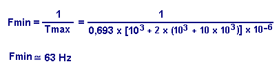
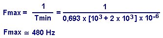
The oscillation frequency is between two limit values : the minimum frequency and the maximum frequency.
To calculate these two values, simply use the following formula :
By turning the adjusting screw to the right (P = 10 kΩ), it is possible to obtain the minimum frequency :
Conversely, turning it all the way to the left, you get the maximum frequency, either :


 Using the C.I. LM 555 to Realize an Astable Multivibrator
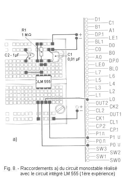
.gif)
.gif)
 Click here for the next lesson or in the summary provided for this purpose.
 Top of page
 Next Page