Using an eight-way Multiplexer to provide the Function of a Gate Network :
11. - TENTH EXPERIENCE : USING A MULTIPLEXER AT EIGHT LANES TO ENSURE THE FUNCTION OF A DOOR NETWORK
So far we have used the multiplexer to switch logic signals. In the following experiment, however, the multiplexer will be used to replace a logic gate network that would have required the use of several integrated circuits.
As an example of application, we will take into consideration the heating installation whose schematic representation is given in Figure 35.
A boiler is fed by two different tanks, one main and one reserve when one of the two valves that regulate the arrival of the fuel is open. This circuit must also indicate whether the main valve and the reserve valve are closed simultaneously.
To detect if the valves are open or closed, two switches S1 and S2 controlled by the valves are inserted in the installation.
To detect the presence of flame in the boiler, a photodiode S0 is used as the sensor. This, in the presence of light, behaves like a closed switch and in the absence of light, like an open switch.
The circuit to be realized will be connected to the photodiode and switches as shown in Figure 36.
When closing a valve, it closes the corresponding switch and the latter ground the input of the control circuit.
When a valve is open, the corresponding switch is opened and a positive voltage is applied to the input of the control circuit through the resistance connected to the "+".
In the same way, the light of the flame makes the photodiode conductive, bringing the corresponding input of the control circuit to the high level. In the absence of a flame, the photodiode is blocked and this same input goes low.
By associating as usual logical state 1 with a high voltage and the ground voltage with logic state 0, the three sensors provide the following information :
S2 = 0
main valve closed
S2 = 1
main tap open
S1 = 0
closed supply valve
S1 = 1
open reserve valve
S0 = 0
no flame
S0 = 1
presence of flame
There may be three different situations, namely :
Everything is normal ;
We are using the reserve ;
The operation is abnormal.
The first situation is true when :
S2 = 0
(main valve closed). No heating during the summer
S1 = 0
(closed supply valve). No heating during the summer
S0 = 0
(no flame). No heating during the summer
or when :
S2 = 1
(main valve open) Heating period
S1 = 0
(closed supply valve) Heating period
S0 = 1
(there is a flame)
Heating period
When we use the reserve, we are in the second situation and we have :
S2 = 0
(main valve closed) Heating period
S1 = 1
(open supply valve) Heating period
S0 = 1
(there is a flame)
Heating period
The third situation (abnormal operation) is true for all other combinations of the three sensors and must correspond to an alarm signal.
The different situations considered are summarized in the table of Figure 37.
Fig. 37. - Operating table of the control circuit.
Fig. 38. - Truth table indicating the input of the multiplexer connected to the output thereof when S0 is connected to control input A, S1 to input B and S2 to input C.
STROBE
S2
S1
S0
Output Y follows the value of the input
0
0
0
0
D0
0
0
0
1
D1
0
0
1
0
D2
0
0
1
1
D3
0
1
0
0
D4
0
1
0
1
D5
0
1
1
0
D6
0
1
1
1
D7
1
X
X
X
Y
= 0
Connect the Y output to the L0 LED. This will be responsible for indicating the three situations ("normal", "alarm", "reserve") as follows :
Normal : L0
off, Y = 0
Alarm :L0
flashes at the frequency of 10 Hz, Y = 10 Hz
Reserve :L0
on, Y = 1.
To achieve these three conditions, it is sufficient to connect the desired signal to the input which is enabled by the combination of the control signals of the multiplexer.
For example, if S2, S1 and S0 have the logic value 0, the L0 LED should indicate the "normal" state and should therefore be off. It is therefore necessary to connect the input D0 to ground.
The different entries will be linked as follows :
Input D0
connected to ground
Input D1
connected to 10 Hz
Input D2
connected to 10 Hz
Input D3
connected to "+"
Input D4
connected to 10 Hz
Input D5
connected to ground
Input D6
connected to 10 Hz
Input D7
connected to 10 Hz.
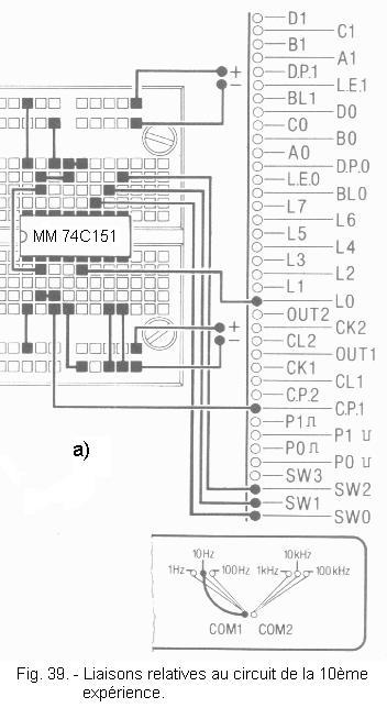
11. 1. - REALIZATION OF THE CIRCUIT
a) Remove from the matrix all the links and integrated circuits used in the previous experiment.
b) Insert the integrated circuit MM 74C151 in the position indicated in Figure 39-a and make connections related to this assembly.
You notice that the control inputs A, B, C are respectively connected to the switches SW0, SW1, SW2. These simulate the switches of the two valves and the photodiode.
SW2 replaces S2, SW1 replaces S1, while SW0 performs the function of the photodiode S0.
11. 2. - OPERATING TESTS
a) Place SW0, SW1 and SW2 on the 0 position.
b) Turn on the Digilab and observe L0 : it is off.
c) When operating the switches, try all possible combinations and check if the situations listed in the following table are true.
SW2
SW1
SW0
L0
0
0
0
Off
0
0
1
Blinks to 10 Hz
0
1
0
Blinks to 10 Hz
0
1
1
Lit
1
0
0
Blinks to 10 Hz
1
0
1
Off
1
1
0
Blinks to 10 Hz
1
1
1
Blinks to 10 Hz
d) After the experiment is complete, turn off the Digilab.
You have thus found that using a single multiplexer, one can realize a montage of a certain complexity.
To realize the savings made by the use of a multiplexer instead of a network of doors, both in the number of components used and in the connection, just look at the diagram in Figure 40 which illustrates one of the solutions allowing to obtain the same result but with logical doors.
The circuit of Figure 40 would require three standard integrated circuits for its realization.
This practice is over, the next one will be devoted to the examination of the memoirs.


 Footer
.gif)
 Click here for the next lesson or in the summary provided for this purpose.
 Top of page
 Next Page