Installation of the Z80 Microprocessor to Test its Operation :
4. 1. - MOUNTING OF THE Z80 MICROPROCESSOR
a)
Remove from the matrix the links and components relating to the previous experiment.
b) Insert on the matrix, at the position indicated Figure 18-a, each of the following components :
Z80 (microprocessor),
74LS74 (double D type rocker),
74LS14 (six Schmitt trigger inverters),
74LS08 (four doors AND),
74LS86 (four doors OR Exclusive),
74LS164 (eight bits shift register),
1 transistor BC559 B,
12 resistors of 1 kW,
1 resistance of 220 W,
1 resistance of 1,2 kW,
1 resistance of 270 W,
1 resistance of 22 W,
1 capacitor of 33 pF,
1 capacitor of 1000 pF
The resistors and condensers are indicated in margin of the Figure 18-a.
When inserting resistors wired to ground, take care that their connections do not touch.
c) Insert the second integrated circuit 74LS74 on the ICX support.
d) Carry out the connections indicated Figure 18-a.
The electric diagram of the circuit carried out is represented Figure 18-b ; by referring to this diagram, systematically check the connections made by adopting the method described above at the end of the assembly of the first experiment.
Make sure that the transistor has been inserted in the correct direction and that the resistance connections do not touch.
The block diagram of the circuit examined is shown in Figure 19 ; the wire leading to terminal An will be successively connected to outputs A0 to A15 which will be tested separately during the experiment.
4. 2. - OPERATION TEST
a) Switch on the digilab.
b) Flip switch SW0 to position 0, then return it to position 1. Thus, the register is reset to zero and all outputs go low. Observe the DIS 1 and DIS 0 displays : they must indicate the number 00.
c) Press P0 : the Z80 microprocessor is initialized. By releasing P0, the Z80 is ready to operate.
d) Press P1 : after about one second, the indication D4 appears. This is the signature of the address bit A0. If the number read corresponds to that expected, this means that the address bit A0 is in the state generated by the Z80 in normal mode. If, on the other hand, the signature read is not that expected, this indicates that the Z80 is not operating regularly.
e) Switch off the digilab.
f) Disconnect from the output A0 (pin 30) of the Z80 the link coming from pin 1 of the 74LS86 and place it at the output A1 (pin 31 of the Z80). The purpose of this new connection is to examine the signature of exit A1.
g) Switch on the digilab.
h) Switch SW0 to position 0 to reset the register, then return to position 1.
i) Press P0, release it.
j) Press P1, release it.
k) Read the signature of A1 which should be : 4C.
l) By repeating the procedure described for A0 and A1, check the signature of the other outputs from A2 to A15. The sequence of operations to be performed is as follows :
We turn off the digilab.
We move the link that goes from pin 1 of 74LS86 to one of the address output pins, the one whose signature we want to note.
The correspondence between the outputs and the pins is :
A2
pin 32
A9
pin 39
A3
pin 33
A10
pin 40
A4
pin 34
A11
pin 1
A5
pin 35
A12
pin 2
A6
pin 36
A13
pin 3
A7
pin 37
A14
pin 4
A8
pin 38
A15
pin 5
We turn on the digilab.
We put SW0 on position 0 then on 1.
We press P0.
We press P1.
We read the signature on the display.
This signature is compared with that of the table in Figure 20.
Fig. 20. - Z80 address signal signature table.
BIT OF ADDRESS
SIGNATURE
DIS 1
DIS 2
A15
8D
A14
E9
A13
4C
A12
54
A11
F1
A10
E9
A9
4C
A8
54
A7
F1
A6
E9
A5
4C
A4
54
A3
F1
A2
E9
A1
4C
A0
D4
If all the signatures correspond to those indicated in the table in Figure 20, this means that the Z80 is functioning properly ; otherwise, it should be considered defective, but this possibility is only very rarely verified.
Anyway, before considering the circuit as defective, it is advisable to check carefully the wiring of the assembly since, in most cases, the error is due to a bad connection.


 Footer
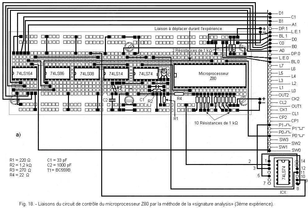
 Click here for the next lesson or in the summary provided.
 Top of page
 Next Page