Study of the Operation of an Asymmetric Oscillator :
7. - FIFTH EXPERIENCE : STUDY OF THE OPERATION OF AN ASYMMETRIC OSCILLATOR
During the third experiment, you could notice that the extinction time and the lighting time of the LED were identical.
Indeed, the output signal of the oscillator is a rectangular signal as shown in Figure 6. Its oscillation period is 1 second. This rectangular signal is symmetrical, being in the high state 1 / 2 second and in the low state 1 / 2 seconds also.
It may be useful to obtain an asymmetrical signal, that is to say whose duration of the high state and the low state are different.
The illumination time of the LED will, for example, be greater than the extinction time.
In this experiment, the realized circuit allows you to obtain such an asymmetrical signal.
7. 1. - REALIZATION OF THE CIRCUIT
a) Disconnect the power supply and remove all the components and connections related to the previously realized circuit.
b) Insert on the matrix an integrated circuit MM 74C14, a tantalum electrolytic capacitor of 1 µF - 10 V, respecting the polarities, a resistance of 2.2 MΩ (red - red - green - gold) and a 470 kΩ (yellow - purple - yellow - gold), in the positions shown in Figure 14-a.
Finally, perform the indicated links.
The Figure 14-b shows the circuit diagram of the realized circuit.
7. 2. - OPERATING TEST
a) Connect the power supply. The circuit starts to oscillate with a frequency of about 1 Hz. Indeed, the LED L0 turns on and off at the same frequency. The extinction and illumination times are about the same, that is, about 1 / 2 second. The output signal is therefore symmetrical.
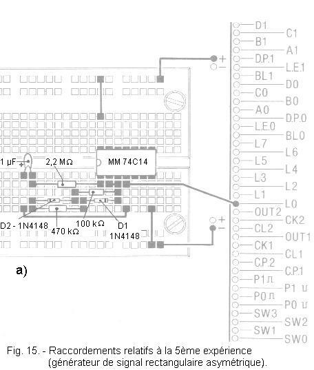
b) Disconnect the power supply. Insert on the matrix a resistance of 100 kΩ (brown - black - yellow - gold) and two diodes D1 and D2 of type 1N 4148. You thus modify the circuit as illustrated in Figure 15-a. The corresponding wiring diagram is located in Figure 15-b.
c) Connect the power supply. The lighting time of the LED L0 is longer than the extinction time.
Indeed, the LED is lit when the output of the circuit is at a level H. Thus, only the diode D1 leads while the diode D2 is polarized in the opposite direction and behaves as an open switch.
The operation of the circuit is then equivalent to that shown in Figure 16-a : its period is about 1 second, the output being in the state H about 1 / 2 seconds.
On the other hand, when the output goes to the level L, the diode D2 conducts and the diode D1 polarized in the opposite direction behaves like an open switch. The circuit becomes equivalent to that shown in Figure 16-b. During this time, the oscillation period is about 1 / 4 seconds.
The duration of extinction of the LED is half this period of oscillation, that is 1 / 8 second.
In this arrangement, the sum of the discharge and charge times of the capacitor is different depending on whether the output is in the H state or in the L state because the resistors in series with the two diodes are different.
d) Disconnect the power supply and interchange the two resistors.
e) Connect the power supply. The lighting and extinction times of the LED are reversed compared to those previously observed.
f) You can test this montage several times by modifying the values of the resistances Ra and Rb. You will observe the variations on the time of ignition and extinction, as well as their periodicity.
This type of circuit generating an asymmetrical signal can be very useful.
You can calculate the oscillation period as follows :
time during which the output is in the state H = 1,1 x Ra x C
time during which the output is in the state L = 1,1 x Rb x C
total period
T = 1,1 (Ra x C) + 1,1 (Rb x C) = 1,1 x (Ra + Rb) x C
You have studied the concept of synchronous logic and the need to have a clock signal to control several circuits at the same time.
You will perform a simple experiment that will help you better understand this concept of synchronous logic.
To achieve this experiment, you will use a new integrated circuit : the MM 74C175 whose diagram is shown in Figure 17-a.
This circuit includes four flip-flops whose CLOCK and CLEAR inputs are common.
Figure 17-b shows the operating table for each D flip-flop. These flip-flops are activated by a rising edge indicated
and applied to the CLOCK input.
The CLEAR input is active at the L level. With this condition, Q is in the L state and
is in the H state, regardless of the logical state of the other inputs (X symbol in the CLOCK and D columns).
8. 1. - REALIZATION OF THE CIRCUIT
a) Disconnect the power supply, remove all components and connections related to the previous experiment.
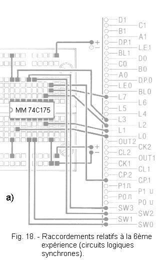
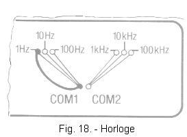
b) Insert the integrated circuit MM 74C175 on the matrix, positioning it as shown in Figure 18-a, then make the indicated connections.
Note in particular the connection between the contacts COM1 and 1 Hz which allows the commissioning of the first clock generator of the digilab.
The realized circuit is shown in Figure 18-b.
The clock input common to the four flip-flops is connected to the contact CP1 where the clock signal of 1 Hz arrives.
The L7 LED is used to display this clock signal.
The D inputs of the flip-flops are connected to the switches SW0, SW1, SW2, SW3 and the corresponding outputs to the LEDs L0, L1, L2, L3.
8. 2. - OPERATING TEST
a) Set the switches to the 0 position.
b) Connect the power supply.
The clock generator operates and delivers a 1 Hz frequency signal indicated by LED L7. LEDs L0, L1, L2 and L3 are off.
c) Observe LEDs L3 and L7 and switch SW3 to position 1.
The Q output of the fourth flip-flop changes to H and LED L3 turns on. The latter only comes on at the rising edge of the clock, indicated by the lighting of L7.
In other words, you observe that LEDs L3 and L7 light up at the same time. LED L3 then remains on because switch SW3 is always in position 1.
d) Try the different combinations that can be achieved with the four switches.
The LEDs corresponding to the switches, in position 1 light up, those corresponding to the switches, in position 0 go out, always at the instant when the LED L7 lights up.
This is an example of a synchronous circuit. That is to say that the four latches simultaneously take into account the four data present on their input at the moment determined by the rising edge of the clock.
Thus, the operation of the four flip-flops is synchronized by a clock signal.
In addition, logical state changes occurring at any time at the entrance of the latches are finally taken into account at a specific time.
This type of circuit makes it possible to synchronize different events that can happen on four logic inputs. This is the case with four switches.
In the next practice, you will equip it with a regulated diet and will make new experiences more and more interesting.


 Functional tests of Synchronous Logic Circuits MM 74C175
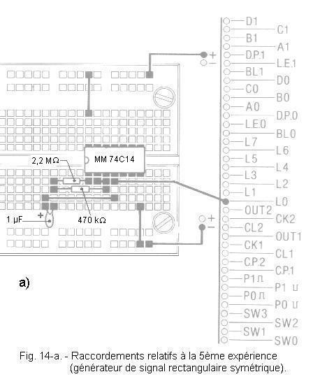
 Click here for the next lesson or in the summary provided for this purpose.
 Top of page
 Next Page