Mounting a Double Clock Generator on the Digilab :
4. - MOUNTING A DOUBLE CLOCK GENERATOR ON THE DIGILAB
You will now perform on the printed circuit of the digilab the installation of two independent oscillator circuits, which can be used as generators of clock signals to later control the circuits experienced on the matrix.
To make the assembly, you will use the support marked by the symbol IC2 in which will be inserted the integrated circuit MM 74C14. The components to be soldered are : six resistors marked R20, R21, R22, R23, R24, R25 and two capacitors marked with the symbols C1 and C2.
The editing procedure is as follows :
a) Disconnect the power supply and remove the connections from the connector group.
b) Disassemble the printed circuit board from its cabinet so that it can easily perform the soldering on the copper side. To do this, also unscrew the fixing screws of the metal front to be able to remove the two red and black power cords of the wafer.
c) After making sure of their ohmmeter value, solder in order on the printed circuit, the following resistors, following the wiring instructions given in practice 1 (Figure 11).
R20 of 12
KW
5% (brown - red - orange - gold)
R21 of
150
kW
5% (brown - green - yellow - gold))
R22 of 1,5
MW 5%
(brown - green - green - gold)
R23 of 15
kW 5%
(brown - green - orange - gold)
R24 of 150
kW 5%
(brown - green - yellow - gold)
R25 of 1,5
MW 5%
(brown - green - green - gold)
d) Then solder on the printed circuit board (PCB) the following capacitors :
C1 tantalum electrolytic capacitor of
0,33 µF - 10 V
C2 ceramic capacitor disk -
330 pF.
ATTENTION: The capacitor C1 must be mounted respecting the polarities of its terminals. The positive terminal marked with the + sign must be inserted in the marked hole + on the printed circuit board. For a correct identification of this capacitor whose value can be also marked with the color code, read in this regard the technical note posted on the boards of equipment or on our site, (see capacitors).
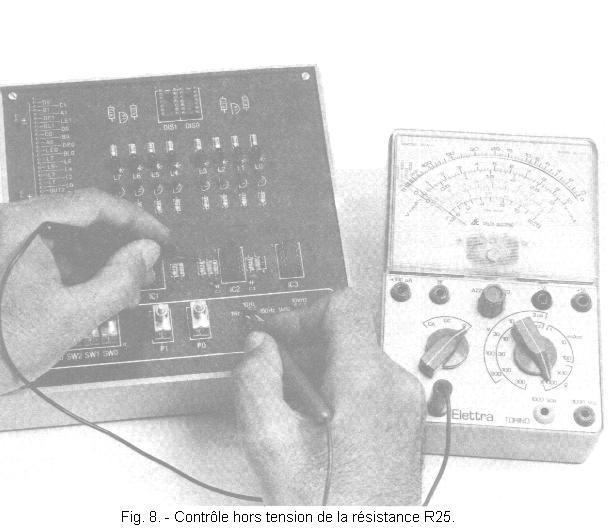
4. 1. - OFF-VOLTAGE CONTROL
First, make sure that the components are mounted on the printed circuit board as shown in Figure 7. Then, prepare the controller for the resistance measurement on the Ω x 1 000. Check that between the contact marked 1 Hz and the upper bound of R25 that you find a value between 1.3 MΩ and 1.7 MΩ. This verification is clearly illustrated in Figure 8.
Then continue with the power off, taking measurements between the points indicated in the table in Figure 9.
Fig. 9. - Control panel off-voltage clock generator.
N°
CONNECTIONS TO BE VERIFIED IN THE OOMMETER
VALUES TO OBTAIN
1
Between the contact 1 Hz and the upper limit of R25
1,3
of 1,7 MW
2
Between the contact 10 Hz and the upper limit of R24
130
of 170 kW
3
Between the contact 100 Hz and the upper limit of R23
13
of 17 kW
4
Between the contact 1 kHz and the upper limit of R22
1,3
of 1,7 MW
5
Between the contact 10 kHz and the upper limit of R21
130
of 170 kW
6
Between the contact 100 kHz and the upper limit of R20
10,5
of 13,5 kW
7
Between the contact COM1 and the terminal + of C1
0
8
Between the contact COM2 and the right terminal of C2.
0
If, during one of these checks, the measured resistance value is not within the indicated limits or is infinite, this means that the resistance in question does not have the expected value or that there is a break.
In this case, check the resistance concerned, the continuity of the copper tracks and ensure the quality of the welds made.
4. 2. - OPERATING TEST
a) Refit the circuit board and the front panel on the box.
b) Remove the integrated circuit MM 74C14 from the matrix and insert it into the support IC2 where it will remain permanently from now on.
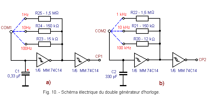
The electrical diagram of the realized circuit is shown in Figure 10. As you can see, it consists of two independent RC oscillator circuits each of which uses two Schmitt rocker inverters and is able to generate rectangular signals of three different frequencies.
Both circuits work as follows :
by connecting the contact COM1 with one of the three contacts marked 1 Hz, 10 Hz, 100 Hz with a piece of wire, you switch on respectively R25, R24, or R23 and the first circuit oscillates in producing a rectangular signal of corresponding frequency. This signal, after passing through a second Schmitt flip-flop providing the "buffer" function between the oscillator circuit proper and the one to be controlled, is available on the marked contact CP1 of the group of connectors.
the second oscillator circuit works in the same way : by connecting the contact COM2 with one of the three contacts marked by 1 kHz, 10 kHz, 100 kHz, you insert the resistor R22, R21, or R20 respectively in the circuit. The signal with the indicated frequency is available on the marked contact CP2 of the connector group.
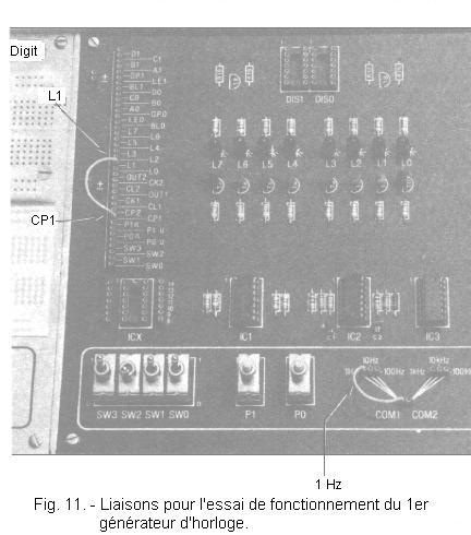
To check the correct operation of both circuits, proceed as follows :
a) Connect contact CP1 with contact L1 of the group of connectors, then contact COM1 with that marked 1 Hz, as shown in Figure 11.
b) Connect the power supply : the first oscillator generates a rectangular signal with a frequency of 1 Hz. In fact, you notice that the LED lights up for 1 / 2 second then goes off for 1 / 2 second and so on. This corresponds to a period of 1 second, therefore at a frequency of 1 Hz.
If the circuit does not work, check the connections, welds and components carefully.
c) Disconnect the power supply and move the conductor connecting the COM1 contact with the contact marked 1 Hz so that the COM1 contact is connected with the 10 Hz contact.
d) Connect the power supply : LED L1 flashes again, but at a much faster rate, about ten times per second.
e) Disconnect the power supply again and connect COM1 with the 100 Hz contact.
f) Connect the power supply : LED L1 lights up and stays on. This should not be interpreted as a malfunction of the circuit : in fact, the circuit generates a rectangular signal with a frequency of 100 Hz.The LED L1 thus lights up and goes out a hundred times per second, and the eye is not more able to appreciate the succession of ignitions and extinctions.
However, you notice that the LED is less bright than usual ; this indicates that in reality it is not always on and that it turns on and off in alternating cycles.
In the next test, relating to the second oscillator, since the frequencies of the generated signal are even higher, it will be practically impossible to ascertain with certainty that the circuit is functioning properly.
Indeed, the LED L1 will present a brightness practically normal. However, you will have the opportunity to perform a more precise control of the correct operation of the oscillators using counting circuits in the next practice.
Now go to the tests of the second oscillator.
g) Disconnect the power supply, remove the previous connections and connect the contact CP2 with the contact L1 of the connector group, as well as the contact COM2 with the contact 1 kHz.
h) Connect the power supply : LED L1 lights up and is slightly less luminous than normal. This indicates that the oscillator is operating, generating a rectangular 1 kHz frequency signal.
i) Then try the operation of the circuit at frequencies of 10 kHz and 100 kHz with the appropriate connections, that is to say by connecting COM2 first contact 10 kHz then contact 100 kHz and observe each time the LED L1. Remember that each time you move the links, it is necessary to disconnect the power supply.


 Footer
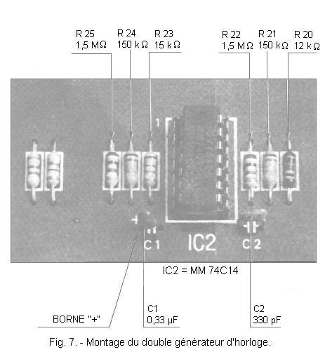
 Click here for the next lesson or in the summary provided for this purpose.
 Top of page
 Next Page