Realization of a Chronometer and Generator of Random Numbers between 1 and 90 :
8. - FIFTH EXPERIENCE : REALIZING A CHRONOMETER
In this experiment, the displays will be used to make a stopwatch of up to 99 seconds.
8. 1. - REALIZATION OF THE CIRCUIT
a) Remove all links and components related to the previous experiment.
b) Insert on the matrix, the modulo counter 16 MM 74C163, the decoder 4 inputs - 10 outputs MM 74C42, the integrated circuit MM 74C00 (quad NAND), the decoder 4 inputs - 16 outputs MM 74C154 and the synchronous counter 4 bits MM 74C193.
c) Perform the connections shown in Figure 25-a.
As this assembly has a high number of connections, use wires of different colors and proceed with the wiring carefully.
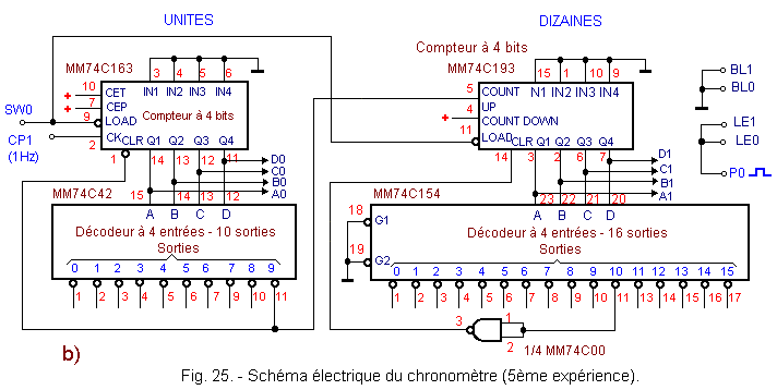
You can make sure that the circuit made reflects the electrical scheme of Figure 25-b.
You notice that this electrical diagram starts to be quite complex.
Indeed, it already includes five integrated circuits, and the overall understanding of the circuit requires some work of reflection.
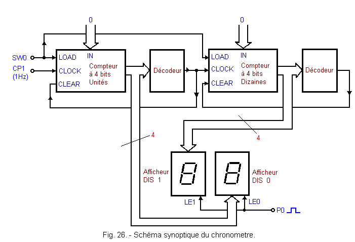
Also, in electronics, we generally use synoptic diagrams that allow a much easier understanding of the circuits.
Figure 26 shows such a block diagram. This is the circuit you just realized.
The fundamental difference from the electrical scheme is the drastic reduction in the number of links.
In this synoptic diagram, you notice that there are two types of links. One is represented by a single line, the other by two parallel lines ending in an arrow.
A single line represents a single electrical conductor (a single link). Two parallel lines represent a set of links of the same type. This is the case of the four outputs of the unit counter.
Sometimes the number of links is indicated. This is always the case of Figure 26 with the four outputs of the unit counter.
It is possible to analyze the operation of the circuit from this synoptic diagram.
The unit counter increments at the rate of one unit every second. When it reaches 9, the output 9 of the decoder attached thereto applies a logic level L on the input CLEAR.
At the tenth active edge of the clock, the counter of the units thus goes to 0 and the tens counter goes to 1 and so on. Each time the unit counter goes from 9 to 0, the tens counter increments by one.
Indeed, the output 9 of the decoder of the units passes on the level L at the level H and thus causes an active rising edge on the input CLOCK of the counter of tens. In parallel with the incrementation of the two counters, the two displays DIS0 and DIS1 indicate the digits at the output of the two counters.
8. 2. - OPERATING TEST
a) Put SW0 on the 0 position.
b) Turn on the digilab.
The two displays indicate 00, because the LOAD inputs of the two counters being at the level L, the counter of the units is prepositioned at 0 during the first positive edge of the signal CP1 (the tens counter is reset to 0 instantaneously).
c) Return SW0 to position 1. From this moment, the stopwatch starts counting the seconds that elapse. The display DIS0 indicates the seconds and the display DIS1 the tens of seconds.
When the counter reaches 99, it returns to 00 at the next clock stroke.
d) Press P0 for a few seconds. You observe that the displays are blocked.
e) Release P0. The counting resumes, not from the number on which it stopped but from the actual number of seconds that have elapsed since the beginning of the count.
Indeed, by pressing P0, the LATCH LE0 and LE1 inputs are activated and the number present at this time is stored. However, the counting continues, which is why when you release the P0 button, the displays show the actual number reached by the timer at this time.
f) Set SW0 to 0. The stopwatch is reset to zero.
g) Turn off the digilab.
This experience has allowed you to see that it is possible to make a stopwatch using specific integrated circuits.
The principle used in digital watches is the same. The two differences lie in the fact that a quartz oscillator is used in digital watches and in the fact that the level of integration of logic circuits is very high. In the experiment that you realized, you use standard and universal integrated circuits, whose applications can be multiple, and for that your assembly occupies a certain not insignificant volume.
Let's now analyze in detail the operation of this montage.
When SW0 is set to 0, the counter MM74C193 loads the binary number present on its inputs, which is 0000 in the present case.
The unit counter loads the same binary number 0000 at the active edge of the clock since the LOAD input is synchronous.
As long as SW0 remains at the 0 position, the unit counter is in load mode and therefore continuously loads 0000 at each active clock edge.
As soon as SW0 is returned to position 1, the timer starts counting the seconds that elapse.
Indeed, the counter of the units is incremented from 0 to 9, at 9 the output 9 of the decoder MM74C42 goes to the level L ; however, this output is connected to the synchronous CLEAR input of the unit counter and to the COUNT UP input of the tens counter.
So at the tenth active clock edge, the unit counter goes to zero since the CLEAR input is at the L level. The DIS 0 display therefore indicates the digit 0. Simultaneously, the output 9 of the MM74C42 decoder returns to the state H and therefore, the tens counter increments by one and thus goes to 1.
Counting continues up to 99.
At the hundredth active edge of the clock, the unit counter therefore returns to 0. The tens counter goes to 10 and the output 10 of the MM74C154 decoder thus goes to 0 simultaneously. So the asynchronous CLEAR entry of the tens counter is activated and this counter immediately returns to zero.
So in fact, the timer goes almost instantaneously from 99 to 00.
The output 10 of the decoder MM74C154 remains only a few tens of nanoseconds at the level L.
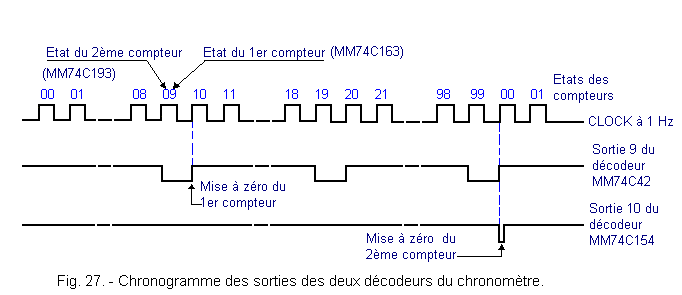
The Figure 27 shows a timing diagram of the operation of the timer relative to the two outputs of the two decoders.
This chronometer is also a modulo 100 counter.
9. - SIXTH EXPERIENCE : REALIZING A RANDOM NUMBER GENERATOR INCLUDING
BETWEEN 1 AND 90
You will now perform a circuit that, once activated, automatically displays a number between 1 and 90.
This circuit is of course a counter whose operation is based on the same principle as that of the previous experiment. It differs only in the fact that it counts up to 90 instead of 99 and that it starts from 1 instead of 0.
9. 1. - REALIZATION OF THE CIRCUIT
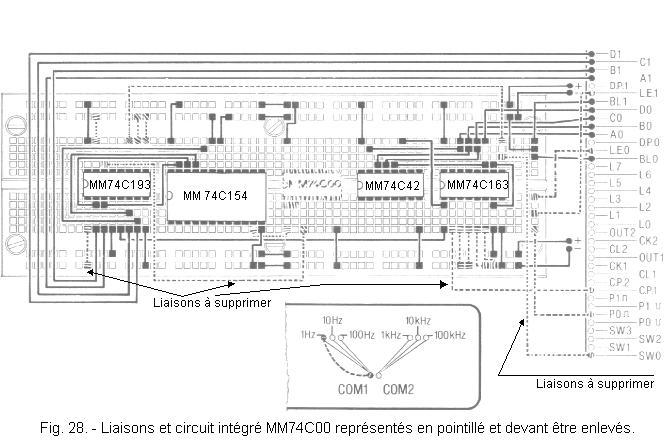
a) Remove from the last completed circuit the links shown in dotted lines in Figure 28.
b) Remove from the matrix the integrated circuit MM 74C00 and put in its place the integrated circuit MM 74C02 (quadruple NOR).
c) Insert diode 1N4148, a 1 µF tantalum electrolytic capacitor (observe the polarity of its terminals) and a 1 MΩ resistor as shown in Figure 29 on the matrix.
d) Make the connections shown in black in Figure 29.
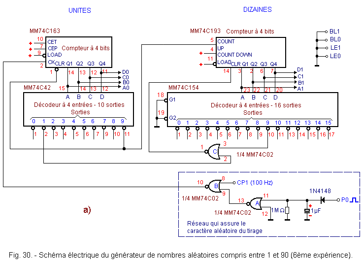
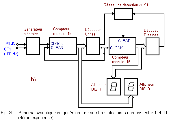
Figure 30 represents the electrical diagram and the block diagram of the realized circuit. These two diagrams differ from those of the chronometer by the presence of the network comprising NOR gates A, B and NOR gate C.
The network comprising the doors A and B is responsible for ensuring the randomness of the drawing of the number.
The gate C makes it possible to reset the tens counter when the ninety-first clock pulse arrives.
9. 2. - OPERATING TEST
a) Connect the power supply : the displays show a random number between 1 and 90.
b) Press P0 : the counter is incremented at the frequency of 100 Hz. You can scroll through the numbers on both displays.
c) Release P0 : after a while, both displays come to rest on a number that is the result of the draw.
Each time you press P0, you make a new draw.
d) Disconnect the power supply.
The circuit under examination has the same structure as that of the fifth experiment. Apart from the fact that it has 1 to 90 instead of 0 to 99, it does not include an initial reset.
For the counter to go from 90 to 01, just decode the number 91 and reset the tens counter.
Decoding is provided by the NOR gate C which receives the signals from the output 9 of the decoder tens and the output 10 of the decoder units.
When these two outputs go to the L level, this indicates that the counter has incremented to 91. Thus, the output of the NOR gate C goes to the H level and thus performs a reset of the tens counter by the entry CLEAR.
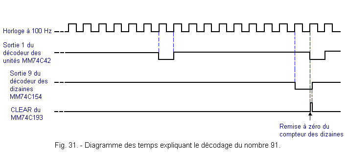
The counter being asynchronous, the circuit remains in state 91 for a short time to go almost instantaneously to state 01, as seen in Figure 31.
The other two NOR gates A and B, together with an RC cell and a diode, are intended to make the draw more random.
When P0 is pressed, a level H is applied to the input of the NOR gate A. This gate being wired in an inverter, a level L is found at its output which validates the NOR gate B. Thus the signal of 100 Hz clock supplied by CP1 is inverted at the output of the NOR gate B and increments the circuit composed of the two counters.
When P0 is released, the voltage at the input of the gate A does not drop immediately because the capacitor of 1 µF takes a certain time to discharge in the resistance of 1 MΩ.
The output of the gate A will only go to level H when the voltage across the capacitor drops below the switching threshold of this gate.
Therefore, the clock signal of 100 Hz can not cross the B door and the count will stop.
The draw is doubly random. First of all, the one that presses P0 can not know to what number the counter has reached (the numbers of the displays are scrolling too fast), then the discharge of the capacitor introduces an additional indeterminacy.
In the next practice, summing circuits and multiplexers will be examined.


 Random Number Generator between 1 and 90
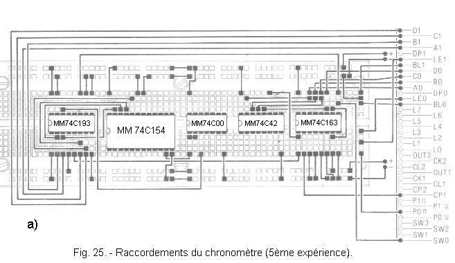
.jpg)
 Click here for the next lesson or in the summary provided for this purpose
 Top of page
 Next Page